Germany: Innovative 3D Printed Scaffold Design for Osteoconductive Bone Tissue Engineering

German researchers take on further challenges and complexities in tissue engineering, releasing their findings in the recently published ‘3D-Printing of Hierarchically Designed and Osteoconductive Bone Tissue Engineering Scaffolds.’
Bioprinting and tissue engineering continues to be a main area of challenge for researchers and medical professionals seeking to improve life for patients requiring critical treatment. Today, scaffolds play a huge role in tissue engineering, and scientists have performed a wide variety of studies, whether in regard to the regeneration of cartilage, growth of tissue after mastectomies, and further experimentation with materials. In this latest study, the scientists are concerned with bone tissue engineering (BTE) for large bone defect treatment (LBDT), developing a new scaffold architecture to serve as a substitute for bone.
As treatment alternatives are ‘urgently necessary,’ the authors seek the best substitute for prompting both bone and vascular formation. Scaffolds must possess the following qualities:
- Mechanical stability
- Absorbability
- Osteoconductive properties
- Osteoinductive properties
- Angiogenic features
- Cytocompatibility
“While promising scaffold solutions for critical size defect treatment in small animals and in vitro exist, successful applications in large animal models have only occasionally been documented and significant innovations for commercially available bone substitutes do not exist,” stated the researchers.
Tissue engineering overall is obviously a difficult science, but as particular obstacles lie in bone regeneration, previous research has shown that the process must be considered comprehensively, not just in ‘partial aspects.’ Cells must be provided with nutrients, oxygen, and cells in different locations must be given special consideration too, such as centrally located cells which may have a poor supply of oxygen.
The researchers used PLA to strengthen the original phase of regeneration, allowing for easy adaption to larger defects. A five-level approach was used, offering mechanical stability along with proper oxygen and nutrient supply for the cells.
Samples for the study were fabricated via FFF 3D printing on an Anet A6, and then characterized when in vitro as well as mechanically.
“While the basic print speed was set to 40 mm/s, depending on the scaffold´s contact area with the bed, a raft or skirt was used for better adhesion,” explained the researchers. “Then, the scaffold was produced with a layer height of 100 µm and retraction distances of 5 mm. To disinfect the scaffold, it was immersed in 70% vol. alcohol for 10 min and subsequently dried for 10 h in a 12 well plate.”
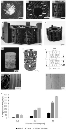
Structure levels in detail (for better illustration of structure details dyed PLA was used here): (a) Close up of a central column. In the center, the filamentary net is visible. Net printing via controlled extrusion, as used for surrounding wall printing, was not possible. Printing parameters had to be adjusted. Flow was decreased and distance between single filaments was increased from 0.1 to 0.3 mm. Althhough filamentary structures are discontinuous, they offer pores in the range of less than 100–150 µm and a high surface/volume ratio. (b) Axial image of single hollow column structure. For better illustration of the wall’s porous fine structure, the solid base ring is missing. (c) Basic unit of this concept: The single column image that inhabits the filamentary nets. The nets are easily accessible through the porous walls varying in diameter. (c,d) Eight hollow columns build up one subunit of the scaffold. At the bottom and top, base rings provide stability for a smooth force transduction. Additionally, the ring is the origin for filamentary Level 2 structures, shown in (a). (c,d) Subunits can be combined via an outsourced clamp system. The rigid truss-like structures were covered with porous walls, to ensure porosity in the range of 300–1500 µm. (f) 3D-printed design alternative: Design 2. (g) A highly porous structure with a central vertical and horizontal channel as well as four rotationally symmetric hollow cylinders. The structure consisted of columns functioning as subunits, which were combined by means of a small pedestal with a ring on the bottom and the top. (h) Dimensions of the second design. (i,j) Microstructures of untreated PLA scaffolds in SEM. Intercolumn areas of the filaments offer narrow spaces (i) and tight cooling cracks (j). (k) Verification of the axial compressive strength of three structural designs and characteristic diameter of struts vs. compressive strength. Test were performed with single hollow columns (diameter: 5 mm; height: 5 mm) (c). Finally, a compromise between strength and material volume was chosen. Experiments were carried out only once for verification of the design. In the future, a validation of the structure with the final design must be carried out. To adapt a scaffold to the size of a critical size bone defect, any number of hollow columns can subsequently be combined on a common base plate. The load is then distributed evenly.
The bone tissue framework consisted of micro-, meso-, and macrostructures mean to offer ‘applicability and surgical use under clinical conditions.’ Levels one through four vary in porosity and structure, while level five is responsible for connection of subunits, to be put together by the surgeon as scaffold dimensions are set—depending on the bone defect size.

Optimized printing parameters for filamentary net structures compared to wall printing parameters.
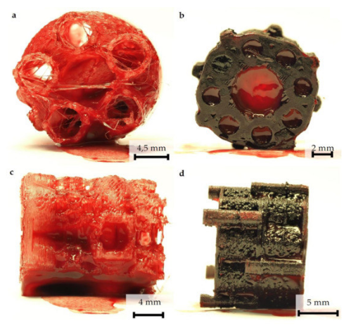
Blood penetration and hematoma formation in both scaffold designs: Each scaffold was immersed in untreated native blood for 30 s. (a) Axial view of design 2 after removal of the frontal cover. (b) Axial view of design 1. (c) Side view of design 2. (d) Side view of design 1. Two scaffolds were combined. The connection via an outer clamp system is clearly visible. The photos were taken after 3-h incubation. A complete wetting of all Scaffold surfaces can be seen. Hematoma formation in both scaffolds is visible in the large vertical (a,b) and horizontal (c,d) channels.
Due to the complex nature of the scaffolds, the researchers realized they could only be fabricated via AM processes. Sample scaffolds were designed in cylindrical shapes due to cross-sectional areas of the bone, along with basic technical aspects. There were issues, however, as necessary pore ranges could not be set. To solve the problem, the researchers filled the areas between the struts.
“Transplantation of a similarly dimensioned, 3D printed, porous hollow column structure into a plate-stabilized 5 mm defect in the rat femur by two authors of this study showed promising healing results,” explained the researchers. “Transfer to a large animal model is conceivable, since current data indicate that scaffolds based on 3D printed fused filament fabrication can be effective for the treatment of large bone defects in large animals.
“For different designs, individualized printing protocols were necessary. Finally, a system with external or internal click brackets proved to be optimal regarding to rotational stability, flexural strength, torsional stability, printability and effect on the bioactive structures. For connectivity, the brackets were combined with the lightweight panels and printed as solid structures. To avoid sharp edges, the transitions between the plates and the plugs were rounded off.”
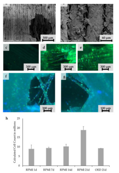
Cell adhesion experiments. Saos-2 cells seeded on undyed PLA scaffolds pretreated with adhesion protein coating: (a,b) Ingrowth of Saos-2 cells into the layers intercolumn and macroscopic pores is visible. (c,d) CFSE staining of native and CellTak pretreated PLA surfaces. (c) Native surface without preconditioning. Only a few cells were adherent. (d,e) CellTak-preconditioned surfaces showed increased cell adhesion. (f,g) CFSE/DAPI staining of Saos-2 cell coated scaffold (Design 2); cells appear green (CFSE) with blue nucleus (DAPI). (f) Stringing in a pore covered with vital cells. (g) Onsight on a pore with stringing structure. On all structural features, multiple vital cells are visible. (h) Calculated cell counts based on MTT-Test results after 1, 7, 14, and 21 days.
Overall, results from the study, offering new structural concepts and design, were considered promising by the research team. They were able to integrate valuable findings from previous researchers—mainly related to stimulation of angiogenesis and osteogenesis—as well as offering a newly ‘refined approach’ that could be improved further with the possible use of a PLA/bioglass (BG) composite.
“In addition, the antimicrobial potential of bioglass proven in vitro could be beneficial,” concluded the researchers. “The effectiveness of an biologically-adapted, bioprinted, and physiologically-enhanced scaffold concept for support of bone defect healing can now be further developed and verified in experimental studies.”
What do you think of this news? Let us know your thoughts! Join the discussion of this and other 3D printing topics at 3DPrintBoard.com.
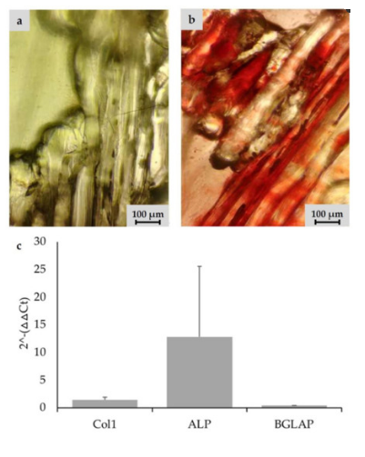
Detection of calcium deposition via alizarin staining on undyed scaffold prototype coated with Saos-2 cells after 21 days: (a) left scaffold was seeded in RPMI-medium; (b) right scaffold was incubated with osteogenic differentiation medium; and (c) PCR results for osteogenic differentiation on Day 21. Saos-2 cells seeded on scaffolds were incubated with RPMI medium and osteogenic differentiation medium. Focus was on cDNA for osteogenic proteins: collagen 1 (Col1), alkalic phosphatase (ALP), and osteocalcin (BGLAP). GAPDH was used as internal standard. The 2−(ΔΔCt) values are presented.
Subscribe to Our Email Newsletter
Stay up-to-date on all the latest news from the 3D printing industry and receive information and offers from third party vendors.
You May Also Like
3D Printing Unpeeled: New Arkema Material for HP, Saddle and Macro MEMS
A new Arkema material for MJF is said to reduce costs per part by up to 25% and have an 85% reusability ratio. HP 3D HR PA 12 S has been...
3D Printing News Briefs, January 20, 2024: FDM, LPBF, Underwater 3D Printer, Racing, & More
We’re starting off with a process certification in today’s 3D Printing News Briefs, and then moving on to research about solute trapping, laser powder bed fusion, and then moving on...
3D Printing Webinar and Event Roundup: December 3, 2023
We’ve got plenty of events and webinars coming up for you this week! Quickparts is having a Manufacturing Roadshow, America Makes is holding a Member Town Hall, Stratafest makes two...
Formnext 2023 Day Three: Slam Dunk
I’m high—high on trade show. I’ve met numerous new faces and reconnected with old friends, creating an absolutely wonderful atmosphere. The excitement is palpable over several emerging developments. The high...