How Do 3D Printed Molds Stack Against Traditional Sand Casting Molds?


Aluminum alloys feature low density, as well as good corrosion resistance and mechanical properties, which is why casting them is an oft-used manufacturing technique. But, defects in molded parts is still an issue. A team of researchers from the University of León published a paper about their work performing a comparative analysis between producing aluminum parts using a 3D printed mold versus the traditional sand casting method.
In sand casting, molds are created by compacting sand around a pattern in a mold box; then, the pattern is pulled out and a cavity in its shape is left. Molten metal is then poured into the cavity to produce components. Reducing porosity, improving the microstructure, and controlling dimensional quality and defects are the three most common issues in casting, but using a properly designed mold can help.
“The manufacturing cost of a mould with complex geometry is one of the main limitations in developing it. However, AM allows the modelling of complex designs, avoiding this limitation,” the researchers explained.
Ceramics 3D printing, based on binder jetting, is “the most suitable for manufacturing cores and inserts” for molds. But most research has only focused on specific parameters, which is why this team focused on how feasible it truly is to 3D print a ceramic mold, and then compared it to a mold made with traditional sand casting.
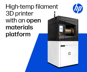
“To prove the usefulness of this modern technology, two different moulds for casting were made: the first was made as a traditional sand casting and the second was made using the 3DP technique. Once the moulds were manufactured, aluminium was poured into them. Then, we analysed the manufacturing time, cooling rate, dimensional deviation, surface quality, surface porosity, and possible defects, comparing both techniques,” they wrote. “With this analysis, we aimed to determine whether the 3DP technique was applicable for aluminium casting, allowing more efficient designs and reducing the cost of production.”
They used an AlSi series casting alloy to design the part, and then designed and calculated the filling system (sprue, well, runner, gates, and riser) for the molds. To study the melt flow’s behavior in order to optimize the filling system, finite element analysis (FEA) was used to simulate filling and solidifying the parts during casting, along with generated turbulence and distribution of the gas entrainment into the liquid. The team used CATIA v5 r21 software to draw a 3D model of the part and both molds, and the molds were then fabricated.
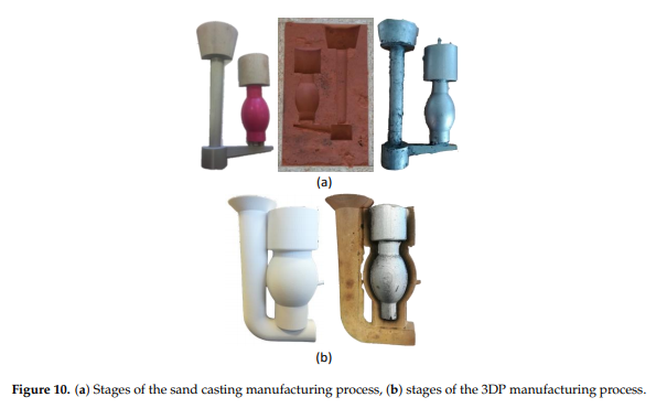
“To manufacture the sand casting mould, a divided pattern was made by the Fused Deposition Modelling (FDM) technique with the Ultimaker 2+ machine,” the team explained. “The pattern contained the part and the filling system.”
A Projet CJP 660Pro from 3D Systems was used to fabricate the ceramic mold using inkjet technology. The aluminum alloy was poured, the melting process took place, and they measured the temperature of the mold “by a K-type thermal couple localized at 2 mm from the mould cavity.”
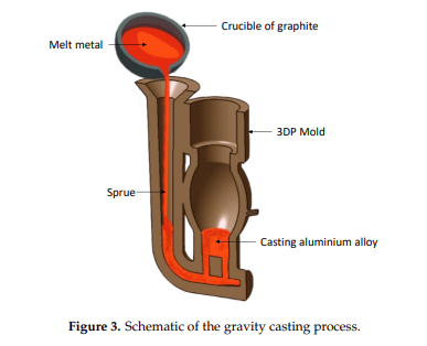
“To achieve proper pouring for the sand casting, it was necessary to fix the halves of the moulds. For the 3DP technique, it was necessary to rest the mould on a sand base to prevent movement during the casting. Subsequently, the metal was poured into the different moulds,” the researchers wrote.
“Finally, the aluminum alloy was solidified and the casting was extracted from both moulds by vibration and crumbling. The filling systems were cut, and the parts were cleaned with pressurized air to begin the analysis stage.”
They compared dimensional quality, roughness, porosity, and general defects, using a Breuckmann Smart SCAN3D-HE structural light scanner to analyze them first, and processing the point clouds with Geomagic Control X software. A profilometer measured the surface roughness, and the molded parts were sectioned and polished with a 3-µm diamond paste, then photographed by a Leica Kl 1500 camera, to evaluate internal porosity. ImageJ software from the National Institutes of Health (NIH) was used to analyze the images.
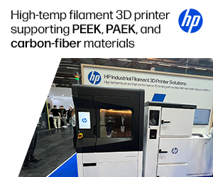
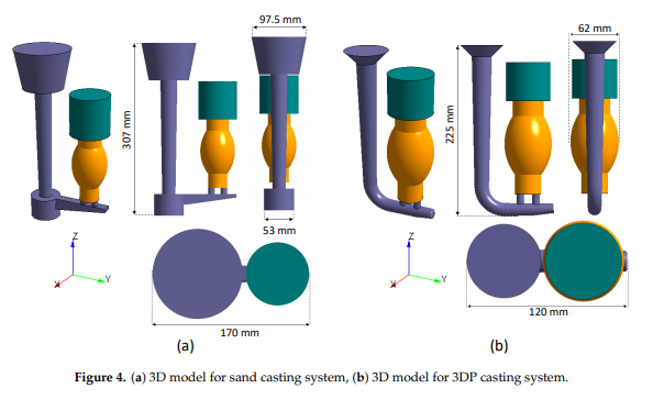
Standard design rules were followed to create the sand mold, which includes a pouring cup and a tapered sprue that ends in a well. But, because of the design freedom that 3D printing brings, that part didn’t need a round geometry to “avoid draft angles” and “obtain a proper pattern removal” without damaging the mold. Additionally, 3D printing allowed the researchers to “optimize the filling system” in the mold.
“Two cylindrical gates were connected to the part cavity,” they wrote. “Due to this improvement, it was possible to eliminate the well and to decrease the dimensions of the filling system, as shown in Figure 2c. The total volume of the 3DP mould was 449 cm3, the metallic yield was 49.75%, and the weight of the mould was 0.55 kg. Compared to the sand casting, the metallic yield was optimized by 29% and the weight of the mould was 95% lower.”
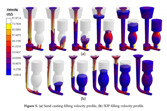
To avoid metal turbulence, oxide films, and gas entrainment, they had to consider the gating speed, which should be no faster than 0.5 m/s during filling. They found that with the sand mold, the speed in the gate increased quickly once the liquid metal had entered the part cavity, which, due to the fountain effect, caused major turbulence. But, with the 3D printed mold, the filling process was homogenous and gate speed remained constant, since they had been able to add an open riser to the design.
Software was used to measure the gating speed at the ingate area’s cross-section during the filling of both molds, and you can see the varying velocities at the ingate center in the figure below.
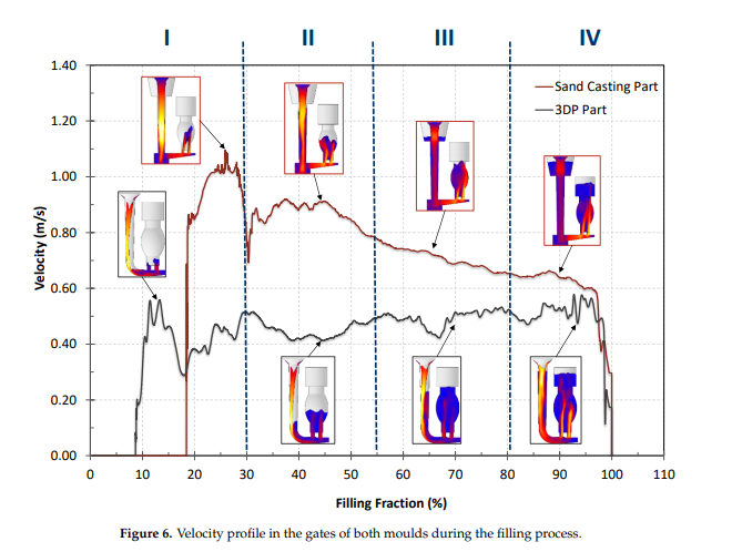
The process had four stages:
- A high input speed generated for both techniques, reaching up to 1.10 m/s in sand casting and 0.55 m/s in 3DP casting
- Speed decreased and stayed constant during most of the filling process at around 0.90 m/s in sand casting and around 0.48 m/s in 3DP casting
- The speed kept decreasing to 0.63 m/s in sand casting, but remained constant in 3DP casting
- The speed remained constant for both techniques with regard to previous values, but majorly diminished while completing the filling process
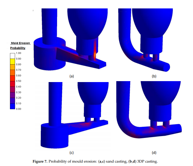
Because of the high speeds in the molds during filling, erosion could generate, causing the affected areas to be ripped away. There’s a higher probability of erosion for sand casting due to the fountain effect, but this decreases with the 3DP mold, because the velocity profile is more easily controlled.
The part then solidifies once the molds have been filled. During filling, the mold temperature went up, and then down during solidification.
“The sand-casting temperature remained uniform in the part cavity at about 710 ◦C,” the team stated. “However, the 3DP mould temperature was about 675 ◦C. A lower cooling rate was obtained in the sand mould due to the low thermal conductivity of the sand and the greater thickness of the mould. In contrast, the lower thickness and higher thermal conductivity of the 3DP mould facilitated the flow of heat.”
It took 5.24 seconds to fill the sand casting mold and 541 seconds to solidify the part, compared to just 2.20 seconds of filling and 378 seconds for solidification with the 3D printed version.
“A lower solidification time means a faster cooling ratio, resulting in higher productivity and better mechanical properties of castings,” they explained.
Additionally, it only took ten hours to fabricate the 3D printed mold, while the sand casting one took nearly 24 hours, as they had to make a two-part pattern and smooth its surface.
Roughness of the part made with the sand casting mold had a mean value of Ra = 3.70 µm in the layer construction direction and Ra = 4.53 µm the opposite way, but while the roughness was even lower in the layer construction direction on the 3D printed part, it was Ra = 7.07 µm in the opposite direction, due to the staircase effect we often see in 3D printing.
“With regard to the dimensional precision, while the staircase effect in the surface of the 3DP mould is the most critical aspect to control, in the sand casting mould the critical aspect is the dimensional precision of the pattern,” the researchers wrote.
In analyzing the dimensional quality, the parts were scanned and Geomagic Control X was used again to process the point clouds. There was an average 0.76 mm deviation between the part and the pattern for sand casting, but -0.43 mm for 3D printing, showing that “the 3DP casting technique can manufacture a more precise part than sand casting.”
Finally, the researchers made a longitudinal cut in the parts in order to analyze what had caused the gas entrapment and bifilm porosities in the castings.
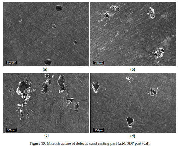
“Microstructures of the cross-section of the moulded parts showed folded shapes and air input in sand casting, which could be produced by the severe turbulence and the oxide film present in the melt during the filling process,” the team explained. “On the other hand, the porosity found in parts produced with the 3DP mould corresponds to shrinkage; during the filling process, the remaining binder is vaporized, creating nucleation points. In this way, pores are formed by shrinkage and a mixture of shrinkage and gas entrapment.”
Surface defects were only spotted on the part made with the sand casting mold, and one of them was the sand itself.
“Sand areas were torn off by the metal stream, floated to the surface, and were then trapped by the molten metal. The main cause of this defect was attributed to an uneven compaction of the mould or a high liquid speed capable of damaging the mould,” they wrote.
The researchers concluded that using 3D printing to fabricate aluminum casting molds was feasible and “adequate” as an alternative to sand casting, as it majorly reduces time and allows for the creation of more complex geometries.
Subscribe to Our Email Newsletter
Stay up-to-date on all the latest news from the 3D printing industry and receive information and offers from third party vendors.
Print Services
Upload your 3D Models and get them printed quickly and efficiently.


You May Also Like
3DPOD 302: Digital Inventory for AM with Mikhail Gladkikh, Würth Additive Group
Mikhail Gladkikh has worked in oil and gas for many years. With this background, we obviously talk about energy market turbulence and the adoption of AM in oil and gas....
Spectrum Filaments Gets Investment: How They Could Win in Filament
Spectrum Filaments is a long-time high-quality filament supplier based in Poland. With good tolerances, roundness, and consistency coupled with affordable pricing, the firm has been a mainstay for makers, industrial...
NX Atomics and Sciaky Collaborating to 3D Print Nuclear Components
For decades, the nuclear industry has quietly experimented with and implemented additive. Bouyed by the likes of ORNL, companies such as Westinghouse have 3D printed components serially. We have an...
Incodema3D Buys 14 Metal EOS Systems, Now One of the World’s Largest Metal 3D Printer Operators
Recently, a majority stake of 3D printing service bureau Incodema3D was purchased by AFM Capital. Under new ownership, the Freeville, New York company is now using its cash-rich parent for...