

Investigating Effects of Process Parameters on Surface Roughness of 3D Printed Down-Facing Surfaces

From titanium bone regeneration scaffolds and hydraulic components to nuclear components and flow reactors, selective laser melting (SLM), which is also known as DMLS and Powder Bed Fusion, is an especially helpful method of metal 3D printing. But there are still some challenges to face before SLM is a true mainstream manufacturing process, such as process repeatability and the fact that so much time-consuming, costly post-processing is often needed for a part to be viable. The surface quality of 3D printed parts fresh off the bed can leave much to be desired.

Visual examination shows significant variations in roughness for the different test pieces.
A collaborative group of researchers from the Karlsruhe Institute of Technology (KIT), Port Said University in Egypt, and 3D Systems recently published a paper, titled “A Study of the Factors Influencing Generated Surface Roughness of Down-facing Surfaces in Selective Laser Melting,” on their investigation of the effects of different process parameters on the surface roughness of 3D printed down-facing surfaces.
The abstract reads, “The aim of this work is to investigate the effect of varying process parameters on the resultant roughness of the down-facing surfaces. The results indicate that the Sz parameter provides greater insight into the quality of down-facing surfaces than the Sa parameter. It is also found that the interaction between parameters are of greatest significance on the obtainable surface roughness, though their effects vary greatly depending on the applied levels. This behavior is mainly attributed to the difference in energy absorbed by the powder, however further investigation is still warranted.”
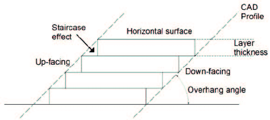
The Staircase effect, up-facing and down-facing surfaces in AM parts
In both up- and down-facing surfaces, SLM 3D printing exhibits what’s called the staircase effect, which can increase their roughness…especially surfaces that face down at less than a 45° angle with respect to the build platform.
“The surface topology of parts produced by SLM are highly dependent on their orientation. This is why, in order to produce parts with good surface quality, down-facing surfaces with angles less than 45° are usually avoided by reorienting the part. Otherwise, there is a need for the building of support structures. However, this in turn results in the increase of process steps, especially the removal of the support could exhibit defects such as burr formation leading to even higher roughness,” the researchers wrote.
This paper looks specifically at the effects of differing build parameters on the surface roughness of down-facing surfaces, in particular when the parameters only change within the plane of the surface facing down and “its immediately adjacent volume.”
“The parameters selected for this research work were the laser power, scan speed and scan spacing. The parameters were varied only for the down-facing surfaces of the build,” the researchers explained. “The remainder of the part was built using the standard build parameters, as recommended by 3D Systems, for a 60 micron layer thickness.”
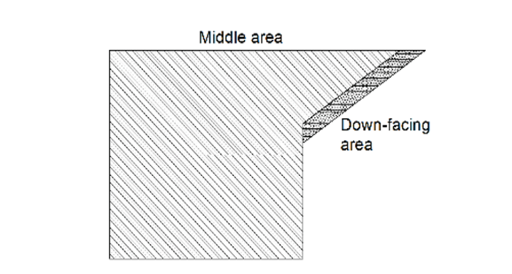
Illustration of areas printed with down-facing parameters
CAD software was used to design the test pieces so they would have a down-facing surface area of 10 x 20 mm, with a 20 mm depth and overhang inclinations of 25°, 35°, and 45°. The test pieces, which were 3D printed on the 3D Systems ProX DMP 320, were designed so they could measure the down-facing surfaces’ roughness with a profilometer.
The results the researchers published in the paper are for the 3D printed test pieces with a 45° overhang angle. At the lower scanning speed, the experiment showed that the laser power didn’t significantly affect the observed roughness parameters. At a lower laser power of 90W, the roughness parameters only increased a little when the scan spacing went up. The team determined from their results that “increasing the scan spacing results in the decrease of roughness values,” for both the low and high values of scan speed.
“Figure 9 depicts the measured Sa and Sz values for all the test pieces. It is clear that the Sa values over the whole square does not exhibit drastic changes across all the tested sample but on the other hand the Sz values exhibit significant deviations though they have similar Sa values,” the researchers wrote.
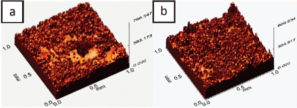
“Fig 10 shows 3D topographies of two surfaces that measured with similar Sa values but display very different surface qualities. The variations in the Sz parameter can be attributed to the disturbance of the surface due to the presence of partially melted powder as well as dross formation that results in high peaks and low valleys resulting in non-uniformity.”
3DPrint.com reached out to researcher Amal Prashanth Charles who explained that,
“Sa and Sz are both areal roughness parameters, so they describe roughness over a particular area. Sa (Arithmetical mean roughness) is an extension of Ra (Mean roughness of a profile) over an area and is generally used to evaluate surface roughness. Sz(maximum height) is the sum of the largest peak height and the largest pit depth within a defined area.”
-

- Fig. 9 (a) 3D surface topography of test piece 7 and (b) test piece 8.
-

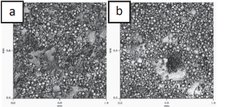
- Fig. 10 (a) Optical microscope image of test piece 3 built with 90W and (b) test piece 7 built with 210W laser power.
The results of the study indicate that, due to its surface non-conformity, the Sz parameter offers more insight than the Sa parameter does into surface quality.
“The presence of partially melted powder and dross formation is the major cause of surface defects within the down-facing surfaces,” the researchers wrote. “Results clearly indicate that for down-facing regions, increasing scan spacing results in lower roughness values, while a higher scan speed increases surface roughness.”
The degree of laser power demonstrated different degrees of effect on the overall surface quality.
“Though relationships begin to arise between parameters, the non-linear behavior and the complex interactions between process parameters add to its unpredictability,” the researchers concluded. “Which makes this process a prime candidate for process modelling and optimization.”
Co-authors of the paper Charles, Ahmed Elkaseer, Tobias Müller, Lore Thijs, Maika Torge, V. Hagenmeyer, and Steffen Scholz.
Subscribe to Our Email Newsletter
Stay up-to-date on all the latest news from the 3D printing industry and receive information and offers from third party vendors.
Print Services
Upload your 3D Models and get them printed quickly and efficiently.


You May Also Like
OVERLEAF 3D Prints Cryogenic Tank For Aviation Liquid Hydrogen
Spanish technology center Aimen has 3D printed a cryogenic tank meant to store liquid hydrogen for use as aviation fuel. This test tank was made as a part of OVERLEAF,...
Low-cost “Suzy” Polymer Powder 3D Printer is Faster and Cheaper than Past Models
Polish laser powder bed fusion (LPBF) firm Sinterit has released a follow-up to its predecessors, Lisa and Nils, called Suzy, a $19,490 printer equipped with a 30W fiber diode laser....
OPPO Find N5: World’s Thinnest Foldable Smartphone Hinges on 3D Printed Hinges
OPPO has unveiled its latest foldable smartphone, the Find N5, demonstrating a significant step forward in the ongoing push for slimmer, more durable foldable devices. With a folded thickness of...
ADDMAN Adds Continuous Composites Technology for Hypersonics and UAV Applications
ADDMAN Group and Continuous Composites are teaming up to reshape how aerospace and defense sectors create parts for hypersonic vehicles and unmanned aerial vehicles (UAVs). Through this partnership, the two...