
G-ID: Identifying 3D Printed Parts Through Slicing Parameters

There are multiple ways to identify specific 3D prints, such as QR codes and bar codes, RFID tags and watermarks, and serial numbers. But a group of researchers from MIT CSAIL and the University of Sussex published a paper, “Demonstration of G-ID: Identifying 3D Prints Using Slicing Parameters,” that takes a different route.
“We demonstrate G-ID, a method that utilizes the subtle patterns left by the 3D printing process to distinguish and identify objects that otherwise look similar to the human eye. The key idea is to mark different instances of a 3D model by varying slicing parameters that do not change the model geometry but can be detected as machine-readable differences in the print. As a result, G-ID does not add anything to the object but exploits the patterns appearing as a byproduct of slicing, an essential step of the 3D printing pipeline,” the abstract states.
This research team actually used the print infill for identification. When you prepare a 3D model for printing, first you have to slice it, i.e. convert the model into layers and a G-code so it can be printed. Because you can modify parameters for slicing “for each individual instance,” the G-ID method is able to create unique textures on the object’s surface, which a camera can later detect.
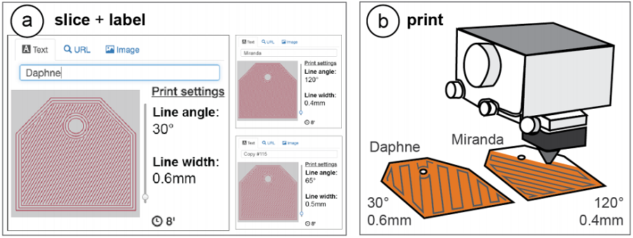

Figure 1: 3D printed objects possess surface patterns due to angle of print path and thickness of trace laid down. G-ID provides (a) a user interface for slicing individual instances of the same object with different settings and assigning labels to them. After (b) 3D printing, users can (c) identify each instance using the mobile app.
“Since our approach allows us to be in control over which printed instance has been modified with which slicer settings, we can identify each instance and retrieve associated labels previously assigned by users,” they explained.
“We introduce the G-ID slicing & labeling interface that varies the settings for each instance, and the G-ID mobile app, which uses image processing techniques to retrieve the parameters and their associated labels from a photo of the 3D printed object.”
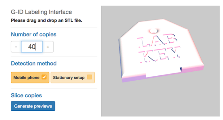
Figure 2. G-ID labeling interface.
The team uses a labeling interface to assign a unique tag to each instance of a print; for the purposes of this experiment, they used forty key covers, “each with an unobtrusive feature that identifies its owner.”
“To assign each key cover a unique tag, we open G-ID’s labeling interface (Figure 2) and load the 3D model of the key cover by dragging it onto the canvas. We enter 40 instances into the left-hand panel of the interface,” they wrote.
The covers are used for the research lab keys, and with the G-ID system, it’s quick and easy to find out who the keys belong to, if they’re missing any at the end of the semester. The G-ID app runs on a mobile device to easily detect the tag of each object.
“We select “Mobile phone” as the desired detection setup. G-ID then slices each instance of the key cover with a unique set of slicing settings,” the researchers explained.
“We can now enter a label in the form of a text, an image, or a URL next to the preview of each instance. Since we want to give each key cover the name of one of our lab members, we enter one name per instance.”
Finally, once they select the “Export” button, the program saves the G-code file for each instance, along with an XML file.
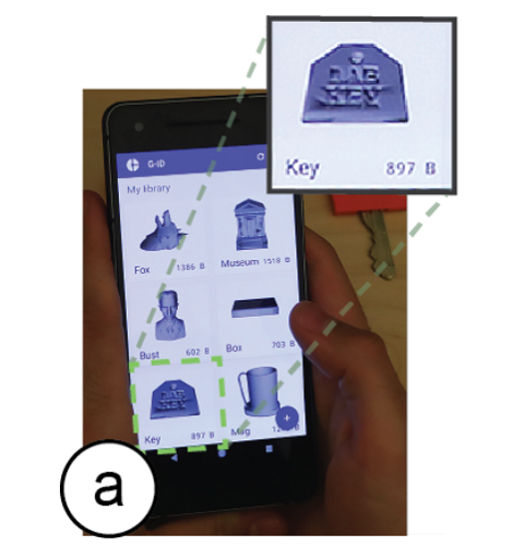
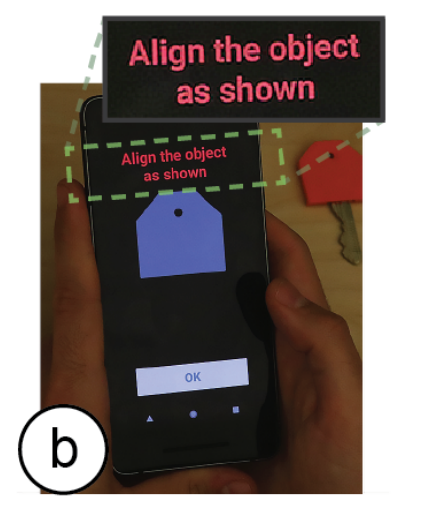
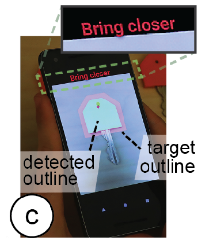
Figure 3: G-ID mobile app for identification: (a) select model from library, (b) face the object, and (c) once outlines are aligned, the app automatically takes the image.
“We now send the G-codes to our FDM printer to obtain the printed instances,” they wrote. “We also transfer the XML file that stores the object information to our smartphone to be used later for identification.”
They choose the correct model to scan using the mobile app, which shows an outline of the object on the screen to help with camera alignment. The image is automatically captured, and the app “identifies the features in the photo associated with the surface-related slicing parameters.” Then, the label is retrieved and shown on the screen…ta-da, object identified!
With the keys, G-ID used slicing parameters that only affected the surface of the object, like the initial bottom line angle and width, since there were only 40 instances. But, for scenarios that need more, the app “can also sense the interior of objects (infill) at the expense of adding a small light source.” They 3D printed 300 coffee mugs to give away during the department’s annual celebration, and using G-ID, the researchers ensured that each mug would automatically fill with the user’s preferred drink when used with a smart coffee machine.
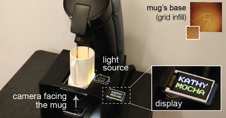
Figure 4. By adding a light, we can detect variations in infill, like different angles, patterns, and densities, which allow for a larger number of instances. The coffee maker recognizes the mug’s infill and pours the user’s drink.
“This time G-ID also varies the parameters infill angle, infill pattern, and infill density once it used up the parameter combinations available for the surface. As users insert their mug into the smart coffee machine, the integrated light makes the infill visible due to the translucent nature of regular PLA 3D printing filament,” they explained. “G-ID takes a picture, extracts the infill angle, pattern, and density, and after identification, pours the user’s favorite drink.”
I humbly request an invitation to the next department party so I can see this cool experiment for myself.
They explained how the slicing parameters were used to label the mugs. For the bottom surface, there are two parameters which influence where the print head’s path goes in the first layer.
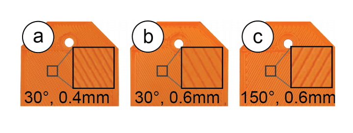
Figure 5. Combinations of different line widths and angles.
“Initial bottom line width defines the width of a single line on the bottom surface and thus the resulting resolution. Initial bottom line angle sets the direction when drawing the lines to construct the surface,” they wrote.
“Infill line distance determines how much the lines of the infill are spaced out and thus determines the internal resolution. The denser the infill lines, the higher the infill density. Infill angle rotates the infill lines according to the direction specified in degrees. Infill pattern allows for different layouts of the print path, such as grid or triangle.”
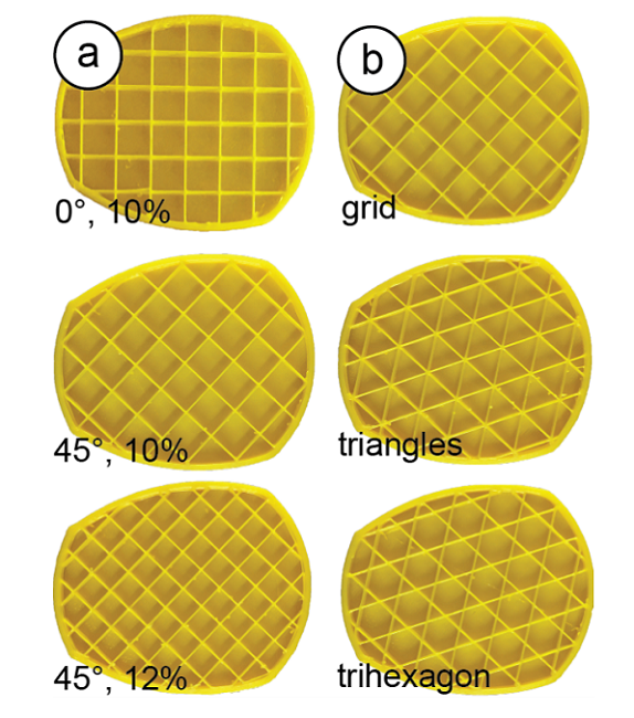
Figure 6: Cross-sections of the mug model show (a) different infill angles and densities and (b) different infill patterns.
Discuss this and other 3D printing topics at 3DPrintBoard.com or share your thoughts below.
Subscribe to Our Email Newsletter
Stay up-to-date on all the latest news from the 3D printing industry and receive information and offers from third party vendors.
Print Services
Upload your 3D Models and get them printed quickly and efficiently.


You May Also Like
AMPulse Asia: Creality IPO Headlines APAC 3D Printing Market Roundup
Asia’s additive manufacturing sector spent the back half of May moving capital and capacity, not just demos. Chinese desktop and consumer printer makers pushed onto public markets, metal powder producers...
Blue Origin’s New Glenn Explosion Comes During Major Manufacturing Push
Blue Origin‘s orbital New Glenn rocket exploded during a hot-fire test at Launch Complex 36 in Cape Canaveral on May 29, setting back the company’s launch ambitions at a time...
Aibuild Says New FETS Simulation Tool Is 10,000x Faster for AM
Aibuild has launched FETS for Additive Manufacturing, a Finite Element Thermomechanical Simulation tool that lets you simulate stress, distortion, thermal effects, and thermomechanical effects. The solution has been optimized for...
AI CAD Tools for 3D Printing: An Overview
There is a bevy of AI-to-CAD tools coming out. Some are finding users; some are raising millions in funding. Many new ones are coming out all the time, so we...