Analyzing & Solving 3D Printing Issues with Microfluidics


In the recently published ‘Microfluidics as a Platform for the Analysis of 3D Printing Problems,’ by Rui Mendes, Paola Fanzio, Laura Campo-Deaño, and Francisco J. Galindo-Rosales, the authors explore FFF 3D printing and the inherent challenges, with a focus on extrusion flow problems and microfluidics as a way to study and solve the issues, along with other problems like misalignment, complete failure of parts, back-flow, and blockage of nozzles overall.
Printing conditions were defined regarding the Deborah number (De), the Reynolds number (Re) and the Elasticity number (El), with the cross-section of each nozzle’s structure copied in a planar microfluidic chip. The researchers constructed these replicated cross-sections with polydimethylsiloxane, and a range of fluids meant to represent a similar elasticity number to polycarbonate.
Design of the nozzle involved a variety of four different scale ratios, with each microchannel possessing an inlet and outlet port.
“Between the inlet and the outlet, there is a contraction that replicates the cross section of the 3D printing nozzle and a sudden expansion to simulate the expansion of the polymeric material when leaves the nozzle and interacts with the atmosphere,” stated the researchers.

Crossing frequency and relaxation time of PC54.
Polydimethylsiloxane (PDMS) channels were created, crosslinked, and then the inlet and outlet ports were constructed with a stainless-steel tip mounted onto a syringe, using a precision tip with an inner diameter of 0.51 mm and an outer diameter of 0.82 mm. THE PDMS were bonded onto a microscope glass, with dimensions examined via SEM images.

“The fluid-flow was characterized by streak line photography, which consists of recording particles displacements over a period of time, allowing a qualitative analysis of the flow pattern,” stated the authors.
“To guarantee a good visualization, small concentrations of particles (40 and 90 ppm) were added to the analog fluid. Instead of using Sodium Dodecyl Sulfate (SDS) to minimize adhesion of fluorescent tracer particles (hydrophobic particles) to the channel walls, a surface treatment to the PDMS with oxygen plasma was applied to each microchannel in order to turn them hydrophilic.”
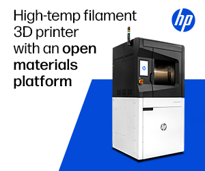
Just the process of creating the microchannels was a task, and the authors pointed out that they had to dedicate a ‘considerable amount of time’ to fabricate a mask without error. With the different scales, however, they were afforded the required flexibility for mimicking printing conditions. Three different conditions were distinguished:
- At lower Reand De, they could observe a laminar profile, with fluid attached to the microchannel walls.
- A second zone showed how the flow was detached from walls upstream of contracting
- Larger vortices caused a preferential central flow path when the Reand De were further increased
“Considering the dimensions of the vortices upstream the contraction, it is possible to conclude that they may be responsible for the back-flow problem in the 3D printer,” concluded the researchers.
“In future works, a wider range of analog fluids should be studied, not only to further complete the flow pattern map, but also to replicate the exact conditions of the printer and to discover the critical Re and De values that potentiate a laminar flow. Another approach could be creating different geometry configurations and analyze if any one of them retards or even prevents the vortex generation. Finally, using all this information, it would be possible to try to replicate numerically the extruding process inside the 3D printing in terms of flow pattern and heat transfer.”
Overall, 3D printing has made a heavy influence on microfluidics, from chip technology to a variety of different scaffolds and portable platforms. What do you think of this news? Let us know your thoughts! Join the discussion of this and other 3D printing topics at 3DPrintBoard.com.
Flow pattern for a Newtonian fluid at different values of Re. The flow direction is from left to right.
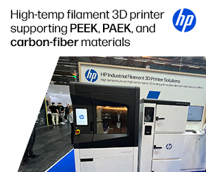
Flow pattern for PAA solutions at El∼375 and different flow conditions: (a) Point 1; (b) Point 2; (c) Point 3; and (d) Point 4 (Table 13). The flow direction is from left to right.
Subscribe to Our Email Newsletter
Stay up-to-date on all the latest news from the 3D printing industry and receive information and offers from third party vendors.
Print Services
Upload your 3D Models and get them printed quickly and efficiently.


You May Also Like
How the World’s Most Advanced Tech Companies Are Using 3D Printing
3D printing has been around for decades. For most of that time, it was a prototyping tool. Engineers used it to check if a design looked right before spending money...
The New Dental Lab: “Three Technicians Can Handle a Hundred Arches,” Says Digital Dentistry Expert Josh Jakson
Josh Jakson’s path into digital dentistry started long before he had a job title. He grew up around it. His father, a Polish immigrant, started the family’s dental laboratory in...
Why Beam Control Could Redefine the Future of EB-PBF
In Part 1, Ulf Lindhe examined how advances in beam control, point melting strategies, and process monitoring are changing the way engineers think about electron beam powder bed fusion (EB-PBF)....
Additive Manufacturing at a Crossroads
Additive manufacturing is at a crossroads. Simultaneously, we find ourselves between certain very different modalities, applications, and industries. Rather than being able to explore them all, companies will now have...