
Variability of Additive Manufacturing Processes Part 5

This is a part of a series of articles: Part One, Part Two, Part Three, Part Four.
Tensile test coupon and check part construction for the six AM processes are described below. FDM The test used the Stratasys Fortus 900mc Aircraft Interiors Configuration with Certified ULTEM 9085™ material. Build parameters were set to the Aircraft Interiors Certification settings. Following the builds, supports were manually removed. Note that material property testing used three discrete batches of Certified ULTEM 9085 to include variances in materials in the overall variability analysis. This was a requirement of the National Institute of Aviation Research (NIAR), under which FDM was tested for the purpose of determining variation and providing a materials dataset. Also note that per NIAR testing standards, 24 tensile test coupons were constructed for XY and ZX orientations. MJF An HP 4200 printer, using the mechanical grade settings for build parameters, produced the test parts in HP’s High Reusability PA 12 material (partially recycled). After removal from the machine, all test parts were media blasted to remove excess powder. Note that five coupons were excluded from the mechanical properties testing because of “jaw breaks” in the tensile testing machine. SLA All test parts were produced in a 3D Systems SLA 7000 using Somos Watershed XC material using the standard build style suggested by DSM (the material manufacturer). Following the builds, test parts were cleaned of excess resin and post-cured for 30 minutes. Note that the SLA 7000 is a legacy printer. However, it was selected for its ability to run Watershed XC, a widely used material. Additionally, the source of the parts confirmed that any differences between the SLA 7000 and the contemporary ProJet 7000 would have minor, if any, effect on the test results. Due to procedural errors, mechanical properties testing used 18 test coupons for the XY orientation and 21 for the ZX orientation rather than the 30 each prescribed in the test plan. However, upon review, the COV results were consistent across the tested coupons, thus making the procedural error negligible.
SLS The test used 3D Systems’ Sinterstation 2500 Plus HS machine with EOS PA2201 material (partially recycled). The build parameters used were those for the 42-Watt setting. Test parts received a media blast, after the build, to remove excess powder. Note that three coupons were excluded from the mechanical properties testing because of “jaw breaks” in the tensile testing machine. Also note that the Sinterstation 2500 Plus HS is a legacy machine, but the source of the parts confirmed any difference from contemporary machines would have minor, if any, effect on the test results.
FFF Markforged’s Onyx thermoplastic material was used for all test parts, which were constructed in a Markforged Mark X printer (which has since been rebranded as X7). The build parameters include a 100-micron slice and triangular infill with default settings. Following the builds, support structures were manually removed. Note that of the planned 30 test coupons for the vertical (ZX) orientation only fifteen were made. The vertical build orientation for a tall, thin part is unsupported, and after review of the fifteen samples, the production of the balance was cancelled. Also note that the check parts had significant warpage (curl) that prevented measurement. To resolve this, the check parts were heated to 100 °C and then fixtured to remove the warpage. Following this procedure, the flatness of the check parts was within 0.050 in. CLIP Carbon’s M1 printer, with its RPU 70 material, was used to create the test parts. After building, all parts were cleaned in an agitated alcohol bath for three to five minutes and allowed to dry for one hour. The parts were then thermally post-cured for four hours at 120 °C. Note that due to the size of the build area, tensile coupons in the horizontal orientation (XY) and the check part were not compatible with the M1.
Test Methods: Mechanical Properties
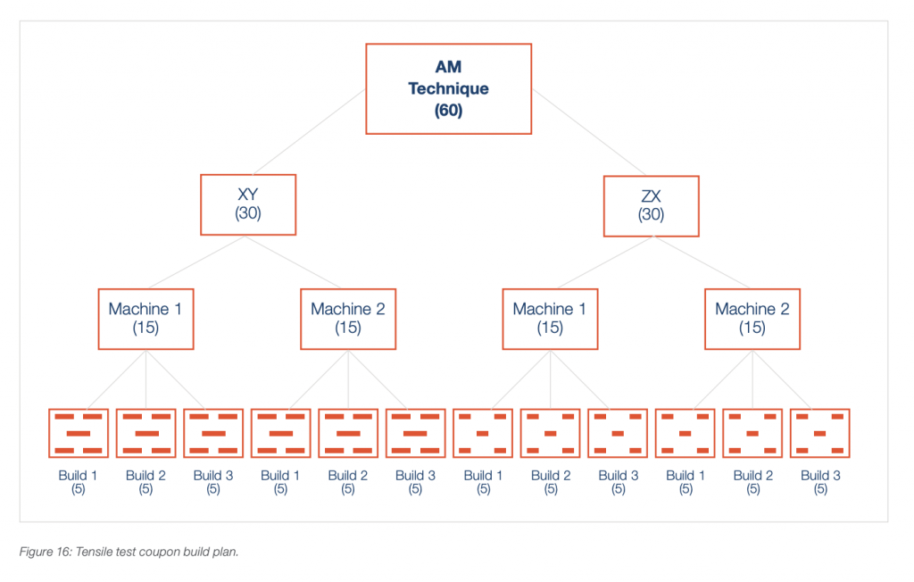
Mechanical properties, including tensile strength, tensile modulus and elongation at break (EAB) were tested by a third-party laboratory according to ASTM D638 testing standards. The coupons (tensile bars) were ASTM D638 Type I with a thickness of 0.130 in. FDM testing was performed in an America Makes program and conducted by RP+M (Avon Lake, Ohio). The testing methodology and procedures followed the National Institute of Aviation Research’s (NIAR) National Center for Advanced Materials and Process (NCAMP) procedures. All testing for the other AM processes was performed by Element Materials Technology (Duarte, Calif.). For each AM process (see Figure 16), 60 coupons were requested. Thirty of these were constructed in a horizontal orientation (flat), which is referred to as ‘XY’. The balance was constructed in a vertical orientation (upright) and are labeled ‘ZX’. To evaluate variation between machines, half (15) of the XY and ZX coupons were built on one machine, and the balance were built on a second machine. Each build contained five coupons, which yielded 12 builds across two machines. The layout for each build was one coupon in the center and one each in the four corners. This layout plan was designed to capture any variation within the AM machines’ build areas.
Variability was evaluated through the coefficient of variation (COV). It is a measure of the relative variability that accommodates comparison when the mechanical properties of the AM materials vary significantly. The COV calculation (below) is the ratio of the standard deviation to the mean (average).
Test Methods: Dimensional Measurements
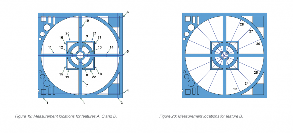
The dimensional inspection was performed with a Mitutoyo QV 606 CMM using a touch probe, which is calibrated annually, and a pre-programmed inspection routine. The inspection routine included 43 separate measurements on 19 features. For each AM process, six check parts were produced in six builds (Figure 17). The builds were split, three each, over two machines. In each build, the check part was located at the center of the build platform and oriented in the XY plane.

The intent of the study was to evaluate dimensional accuracy and precision across the extents of the processes’ build areas. Therefore, testing used a check part measuring 9 in. x 9 in. (Figure 18). Due to the significantly smaller build area of the CLIP M1 machine, versus others in this study, this study design element prevented dimensional inspection for CLIP.
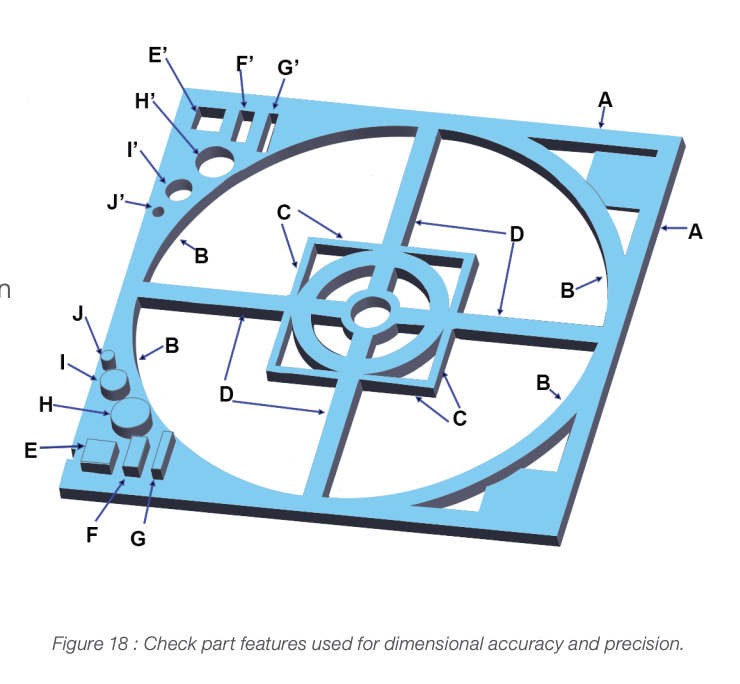
The check part has three categories of features’ for inspection: large; small, positive; and small, negative. The large features, labeled A, B, C, and D in Figure 18, were measured in multiple locations along both the X and Y axes. Note that for features C and D, the dimensional analysis considers the wall thickness, not the overall size. Figures 19 and 20 show the location of each of these measurements.
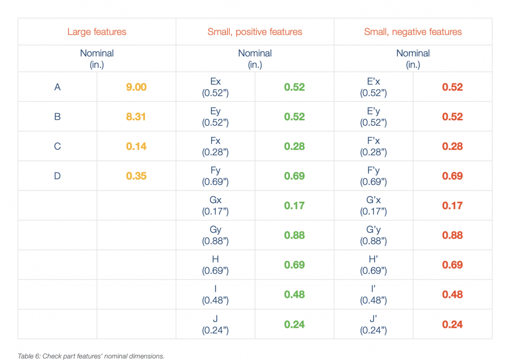
The small features are mirrored along the centerline (X axis) of the check part, and they are reversed to have identical features that are both positive (cylindrical bosses and rectangular standoffs) and negative (holes, slots and cutouts). The small, positive features are located on the lower left of the check part. These are labeled in Figure 18 as E, F, G, H, I and J. To indicate the axes of measurement, each label has an ‘x’ or ‘y’ appended to the labels for rectangular features. The small, negative features are located on the upper left. These features use the same labeling convention as that for the positive features with the addition of a prime symbol (‘). The locations of the measurements for small features are shown in Figures 21. Note that due to impediments to the CMM inspection routine, three measurements were omitted, H, G‘x and G‘y. Feature H, a cylindrical boss, was eliminated after discovery of a CMM programming error that caused the touch probe to contact feature F. Feature G’ was too narrow for the CMM touch probe to enter.
This article was written by independent 3D printing consultant Todd Grimm, a long-standing industry expert. The research was however conducted for Stratasys.
Subscribe to Our Email Newsletter
Stay up-to-date on all the latest news from the 3D printing industry and receive information and offers from third party vendors.
Print Services
Upload your 3D Models and get them printed quickly and efficiently.


You May Also Like
Srini Kaza Discusses Strategically Scaling Align’s “Smile-Changing” 3D Printed Aligners
Align Technology‘s Invisalign is a revolutionary method to get you the smile you want through 3D printing. It is also a hugely popular process to go through, a $4 billion...
Analysis: Additive Manufacturing Strategies Spotlights Vertical Value Creation
A slowdown in the industry and particularly a tightening of access to capital following the additive manufacturing (AM) industry’s peak special purpose acquisition company (SPAC) phase in early 2021 is...
Department of Defense Awards PROTECT3D $1.3M for Custom 3D Printed Braces
Custom prosthetics company PROTECT3D has secured a $1.3M Department of Defense (DoD) Small Business Innovation Research contract to develop a platform for creating custom braces for soldiers. The PROTECT3D Platform...
AMS 2025 Highlights Big Changes in 3D Printing with Pivotal Speakers and Panels
2023 was filled with excitement around the potential mergers being pursued by industry stalwart Stratasys (Nasdaq: SSYS), leading to some of the most insightful conversations imaginable at Additive Manufacturing Strategies...