
Novel Retroflective Fibers Made Through 3D Printing

In ‘Fabrication and measurement of 3D printed retroflective fibers,’ authors Michael Ghebrebrhan, Gabriel Z. J. Loke, and Yoel Fink are engaged in studying novel materials for additive manufacturing processes. With a new retroreflective fiber, the authors offer a material combination with a previously unheard of complex (non-circular, non-convex) cross-section that also exhibits optical scattering properties. This new kind of fiber is built up layer by layer but can subsequently be used as a fiber would.
As thermal drawing becomes more popular again for creating complex fibers, researchers make use of polymers, metals, elastomers, and more. For this research project, they created a 3D printed preform meant to retroreflect light—or as the authors explain, ‘the angle of reflection is the negative of the angle of incidence.’ The preform is made of polymer and metal (polycarbonate (PC) and indium), with the fiber acting as the element that retroreflects light.
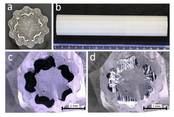
a) Top view of the 3D printed polycarbonate (PC) preform with five indium strips in
the channels. The outer cross-section of the preform contains a curvy serpentine outline. b)
Side view of same preform. c) Epoxy-embedded drawn fiber under a microscope (transmitted
light image). d) Same sample but reflected light. Both images in c and d illustrate the same
curvy serpentine indium architecture as that constructed in the preform
“Glass beads on a reflective surface are a familiar example of a retroreflective surface,” state the researchers. “To maximize retroreflectivity, the polymer’s refractive index should be close to 1.9. At that index, a cylinder or sphere will refract light towards the intersection of the optical axis and back surface.”
The preforms were 3D printed on a Stratasys Fortus 450MC printer, with infill at the highest setting as attempts to increase it otherwise failed; the issue with indium is that it is so much more dense than PC, and the preform must be able to resist deformation.
“Hence a print path that traces multiple concentric paths should be used to counteract the outward hydrostatic pressure from the liquid indium for preserving the cross-section and preventing pooling (lumping) of indium in the draw furnace,” state the researchers.
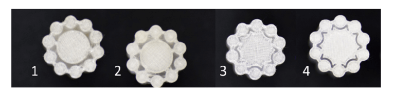
Evolution of 3D printed preform cross-section: 1) two bridges to connect outer ring to inner PC core, 2) five bridges to reinforce outer ring, 3) similar to 2 but reduction of channel volume to reduce indium volume and outwards stress during draw, 4) similar to 3 but with thicker bridges for further reinforcement.
As the researchers worked to stop pooling of indium, they lowered dwell time and maximum temperature as much as possible. They did, however, find that because the preform is 3D printed, strength was not as high as in comparison to a solid rod. Because of that, its viscosity had to be lower than a solid preform—created with a preform that includes a ‘long solid bottom.’
One part of a fiber with five filled channels was then taken for retroreflection. As light was focused on the fiber, the team recorded intensity with a spectrometer.
“As our figure of merit, we calculate the amount of light retroreflected by a single fiber relative to that of a white reflecting standard. Both are then scaled by the intercepted area. This yields a rescaled relative retroreflection ratio (RRR),” concluded the researchers. “Across the visible spectrum we obtain a rescaled RRR of roughly 260.
“Complex cross-section preforms are easily attainable with additive manufacturing and future efforts will explore the addition of multiple materials.”
The study of materials continues to become more complex in 3D printing, and especially with composites—from continuous fiber to wire polymers, flax biocomposite, and countless others. What do you think of this news? Let us know your thoughts! Join the discussion of this and other 3D printing topics at 3DPrintBoard.com.
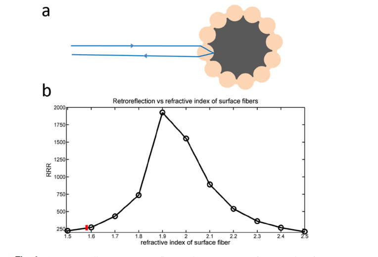
. a) Ray-trace illustrating retro-reflection. b) RRR versus refractive index of outer
ring. The red line indicates our fiber (n = 1.58, RRR = 260). The peak RRR value occurs for a refractive index just over 1.9.
Subscribe to Our Email Newsletter
Stay up-to-date on all the latest news from the 3D printing industry and receive information and offers from third party vendors.
You May Also Like
Profiling a Construction 3D Printing Pioneer: US Army Corps of Engineers’ Megan Kreiger
The world of construction 3D printing is still so new that the true experts can probably be counted on two hands. Among them is Megan Kreiger, Portfolio Manager of Additive...
US Army Corps of Engineers Taps Lincoln Electric & Eaton for Largest 3D Printed US Civil Works Part
The Soo Locks sit on the US-Canadian border, enabling maritime travel between Lake Superior and Lake Huron, from which ships can reach the rest of the Great Lakes. Crafts carrying...
Construction 3D Printing CEO Reflects on Being Female in Construction
Natalie Wadley, CEO of ChangeMaker3D, could hear the words of her daughter sitting next to her resounding in her head. “Mum, MUM, you’ve won!” Wadley had just won the prestigious...
1Print to Commercialize 3D Printed Coastal Resilience Solutions
1Print, a company that specializes in deploying additive construction (AC) for infrastructure projects, has entered an agreement with the University of Miami (UM) to accelerate commercialization of the SEAHIVE shoreline...