
A Holistic Approach to Metal 3D Printing Process Selection for Aerospace Parts

Summarized by Tessa Fedotowsky, Paul Gradl, Darren Tinker
NASA Marshall Space Flight Center
Metal additive manufacturing (AM) use in the aerospace industry has become more prevalent in the last decade for development and flight applications. The metal AM processes available for casting or forging replacements, repair, or complex component builds is expansive. How to determine the best AM process for a candidate part is neither well-documented nor naturally intuitive. There are many technical and programmatic advantages of using AM for the aerospace industry. Technical advantages include reduced mass, complex geometry (not feasible with traditional manufacturing), enhanced heat transfer, part consolidation, and use of novel high-performance alloys. Programmatic advantages include reduced part lead times and cost, rapid design-fail-fix cycles, faster time to market, reduced scrap material waste, and lower buy-to-fly ratio. Despite the many advantages of AM, it may not be better than traditional manufacturing for some applications and should be evaluated for each part and production rate. Novelty and lack of material certifications for some AM alloys may discourage selection regardless of potential benefits. It is important to trade not only between the AM processes but also between traditional manufacturing.
NASA engineers recently released a journal article (Robust Metal Additive Manufacturing Process Selection and Development for Aerospace Components, Gradl et al.) summarizing a holistic approach of metal AM process selection and how to successfully implement AM use for aerospace components. The article gives insight into each phase of the AM lifecycle and provides a foundation for engineers and teams to analyze and down select the optimal AM process for their application. A synopsis of the article is presented here.
AM Lifecycle
A trade study is required to select the optimal AM process for a part, and it starts with a full understanding of the component’s entire lifecycle. The iterative — and highly integrated — lifecycle steps for AM aerospace components are (1) design and pre-processing, (2) build process (including process parameters and feedstock), (3) post-processing, and (4) part in service and qualification. Each lifecycle step (and their sub-steps shown in Figure 1) influences the process selection, steps required, and impacts the final part performance.

Fig. 1 Major process steps in the iterative lifecycle for AM aerospace components
Design and Pre-Processing
The design step not only includes the typical design process, but also design for AM and model verification (i.e., model checks and part interrogation) to make sure the exported model matches the original design intent. The design and pre-processing step alone may be heavily iterative in the AM lifecycle, well prior to the manufacturing step. All subsequent steps in the AM lifecycle must be considered in the design and may include print features for fixturing, machining datums, ports for powder removal, or undersized or oversized stock for finishing operations such as polishing. The entire AM process should be conceptualized and included in the design phase to minimize cost and iterations.
Build Process
AM processes often have differing energy sources, input parameters, and feedstock requirements, which further opens the design trade space. The article focuses on AM processes that have been (or are being) used in current flight applications. Examples of such metal AM processes are shown in Figure 2. These process categories include powder bed fusion (PBF), directed energy deposition (DED), and solid-state processes, such as cold spray (CS), additive friction stir deposition (AFS-D), and ultrasonic additive manufacturing (UAM). These processes have been used for repairs, coatings, and freeform part fabrication; and each has unique advantages and limitations. While many examples exist across the industry, the dominant process being used is laser powder bed fusion (L-PBF), followed by DED (including both laser wire DED (LW-DED) and laser powder DED (LP-DED). The maturity of each AM process is increasing rapidly. The AM processes are often supplemental to each other and can be used in conjunction with one another to minimize overall part cost and performance.
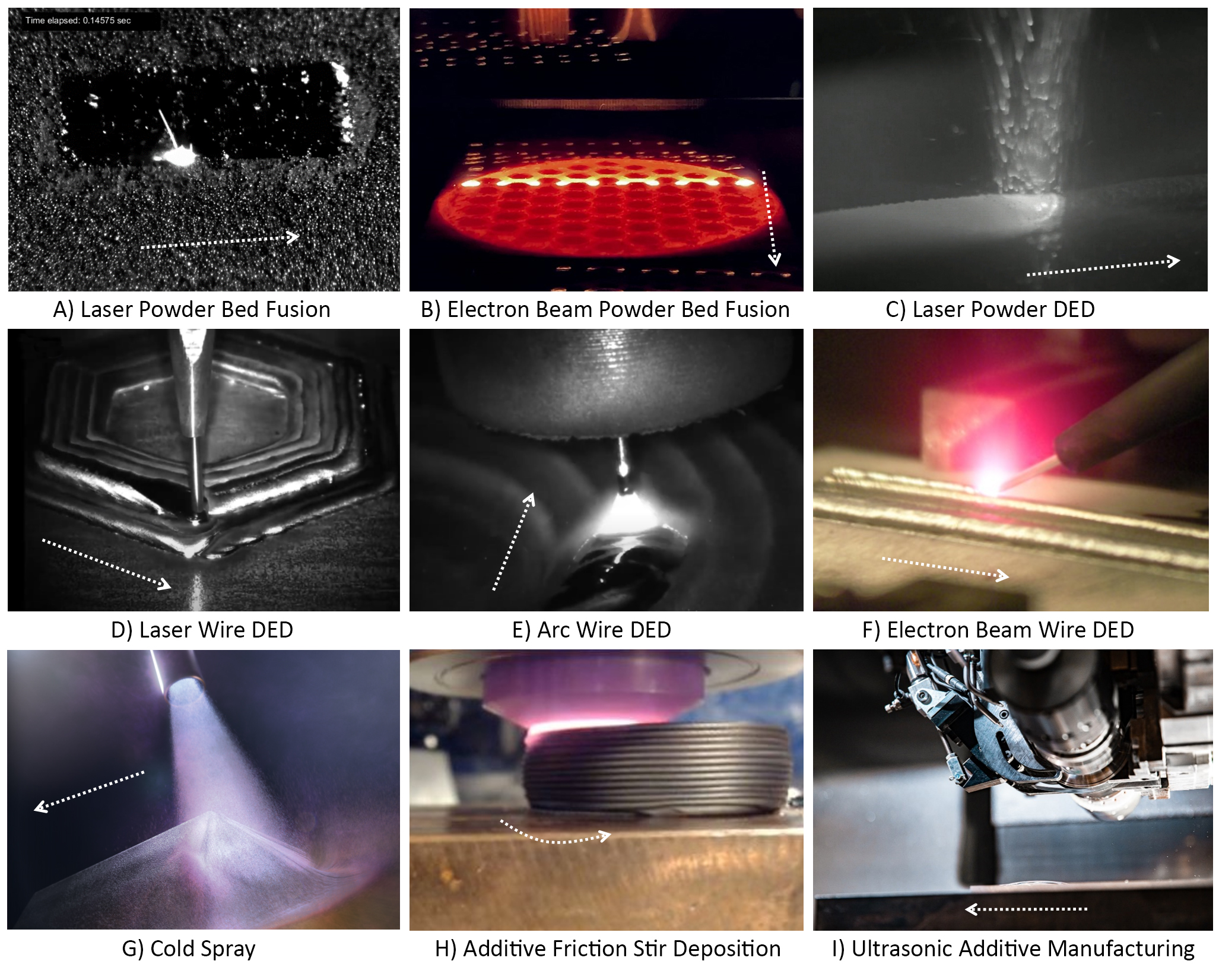
Fig. 2 Closeup images of the various metal AM processes along with deposition/build direction. (a) Laser powder bed fusion (Ref), (b) Electron beam powder bed fusion [Credit: Courtesy of Freemelt AB, Sweden, www.freemelt.com], (c) Laser powder DED [Credit: Formalloy], (d) Laser wire DED [Credit: Ramlab and Cavitar], (e) Arc wire DED [Credit: Institut Maupertuis and Cavitar], (f) Electron beam DED [Credit: NASA], (g) Cold spray [Credit: LLNL], (h) Additive friction stir deposition (Credit: NASA, MELD), (i) Ultrasonic AM [Credit: Fabrisonic]
Post-Processing
Post-processing is critical to ensure each part meets the final design intent. There are often several post-processing steps involved including powder removal, build plate removal, heat treatments, machining, inspections, cleaning, joining, and surface polishing. Proper heat treatments eliminate residual stresses and improve the material properties necessary for its final application. The post-processing steps must be tailored individually for each part, material, and manufacturing method.
Part in Service and Qualification
Placing a part in service includes final assembly, testing, part qualification effort, and production planning. The part-in-service step requires detailed integration by knowledgeable engineers in all aspects of the AM lifecycle (the design, pre-processing, build process, and post-processing) in order to meet part requirements. This may involve design iterations prior to locking down the process, which provide opportunities to optimize the process selection and achieve performance goals.
Trade Factors for Process Selection
The trade factors for AM process selection are organized into four main areas: (1) design features, (2) process inputs, (3) process limitations and considerations, and (4) metallurgical and geometric considerations. Design features include alloy selection, overall part size, and feature resolution. Process inputs include type and attributes of feedstock (chemistry, particle size distribution, wire diameter, etc.) and detailed parameters. Process limitations and considerations include the use of single or multi-alloy, process economics, process availability, and industrial maturity. Geometric and metallurgical considerations include post-processing (including machining for mating flanges, polishing, etc.) and metallurgical characteristics that result in the final properties. These trade factors are shown in Figure 3. The most common basis for process selection is the complexity and scale of the component.
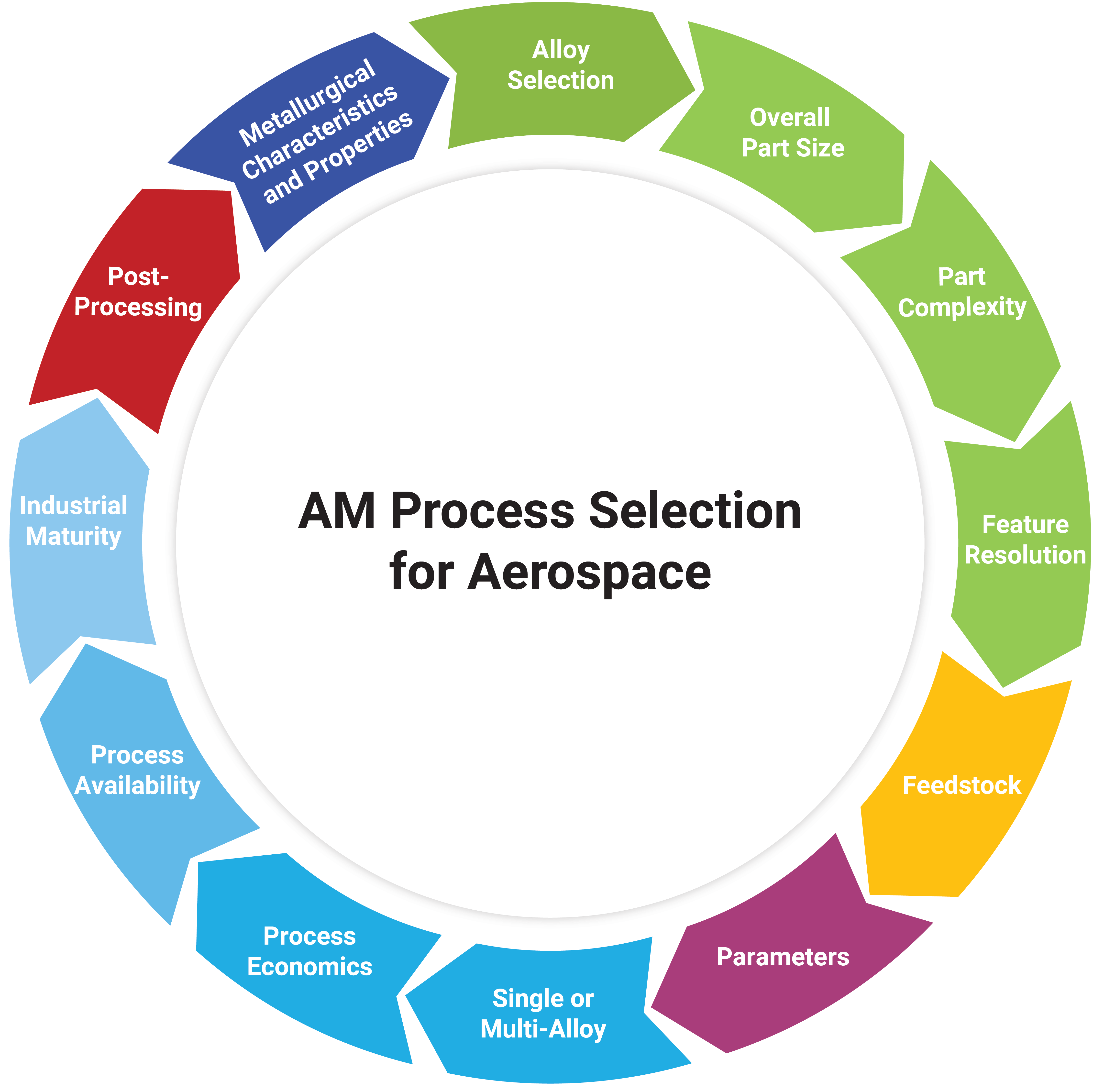
Fig. 3 Process selection attributes for aerospace components. The colors align with process steps in Fig. 1.
Design Features
Alloy selection is generally accepted as the initial input for process selection, narrowing the potential feedstocks and starting the analysis of process availability. Not all alloys are available for the processes and alloy properties will vary. The aerospace AM metals include aluminum alloys, stainless steels, titanium alloys, nickel-and iron-based superalloys, copper alloys, and refractory alloys; specific alloy details are provided in the full article.
The overall part size may prematurely drive process selection. A process chosen for build volume alone is not guaranteed to meet the requirements for performance, feature resolution, or material properties for the final part. Continual evaluation of the state of the industry is needed to determine current build volumes for processes. The build volumes of AM processes have substantially increased in the last 6 years with some processes now capable of build volumes up to 9-meter height and 5‑meter diameter.
The feature resolution for each AM process has ranges and is highly dependent on the feedstock, machine hardware configuration and process parameters. A graphical summary of the feature resolution compared to deposition/build rate is shown in Figure 4. Not all AM processes were designed for the highest feature resolution, and many process are intended to provide high rates of deposition as a forging or casting replacement and reduce overall build cost.

Fig. 4 Selection of process based on feature resolution, build/deposition rate and multi-alloys builds. AFS-D image credits to MELD Manufacturing, Cold spray image credits to Spee3D, EBW-DED image credits to Sciaky and Lockheed Martin Corporation, AW-DED image credits to Gefertec, LW-DED image credits to Meltio, UAM image credits to Fabrisonic and NASA JPL, LP-DED image shows a Ni-based part manufactured by LMD-p during the DEPOZ project led by IRT Saint-Exupery and Formalloy, L-PBF image credits to Renishaw plc and CellCore GmbH/Sol Solutions Group AG, EB-PBF image credits to Wayland and GE Additive/Arcam. Black text represents melting processes while blue text represents solid-state processes
Process Inputs
A designer must also consider the supply chain for metal AM, explicitly for the starting feedstock and the AM processing machine. Regardless of composition, form, or novelty, feedstocks may be long-lead time and must be considered when evaluating the entire supply chain. Powder feedstock requirements depend on the AM process and must be controlled to the chemistry and particle size distribution (PSD) to ensure flowability and spreadability. Other feedstocks such as wire, barstock, or foil may be readily available for common alloys, but may have longer lead times or greater costs for custom alloys.
Most AM processes allow for multiple alloys, although metallurgical characterization and full implementation into flight applications for multi-alloy AM components is limited to date. Builds with multiple alloys can be optimized for mass, thermal, structural, or other design features and can eliminate or reduce joining or post-print assembly operations.
Process Limitations and Considerations
Complexity comes at many implicit costs due to increased build time, build features, or necessary post-processing operations. Further, the inspectability often decreases as complexity increases. Complexity creates challenges in the post-processing operations such as powder removal, machining, polishing, and inspection and should be evaluated throughout the lifecycle. As deposition rate increases, the cost can decrease, but feature resolution is also reduced. The cost trade among AM processes must include the as-built complexity and post-processing steps required. For example, a near net shape part might be built quickly with high deposition rates, but additional machining time is required due to extra stock.
The most used metal AM process is L-PBF with machine availability across hundreds of companies and service vendors. There are many more suppliers available for producing parts using L-PBF, compared to LP-DED. LW-DED and arc wire (AW)-DED both have a limited commercial supply chain of service vendors. Cold spray has limited process machines for production, but the market is growing with new machine manufacturers. AFS-D and UAM are less developed compared to many of the other processes with a handful of machine vendors, but research and industrialization is rapidly maturing across all processes.
Some of the AM processes are more mature than others due to early industry adoption, standards development for flight applications, and the evolution and characterization of the materials used, which increased the technology readiness levels (TRL). For hardware qualification, the process parameters must be controlled and shown to be consistent and repeatable, which is tied to the industrial maturity. All the processes have been used in development applications including test and shown at a TRL 5, where several have also reached flight applications and TRL 9.
Metallurgical and Geometric Considerations
As metal AM processes mature and are being used for aerospace components, the understanding of microstructure response to process parameters, feedstock, and machine inputs must advance. Material properties are highly dependent on the feedstock, the process itself, and the post-processing methods, such as heat treatments. A change in the processing of the metal will have significant impacts on the microstructure and the material properties. Based on the state of the material, heating and cooling rates, or cold working during build operations, each process results in a different microstructure. Before implementation into a flight application, the build parameters and feedstock must be well-understood and locked and microstructure evaluated throughout the evolution of heat treatments and post-processing. An example of as-built microstructures from the AM processes is shown in Figure 5. Increased understanding of AM process influence factors on material microstructures and properties will support material performance optimization and improvements in certification approaches for aerospace qualification of AM parts.
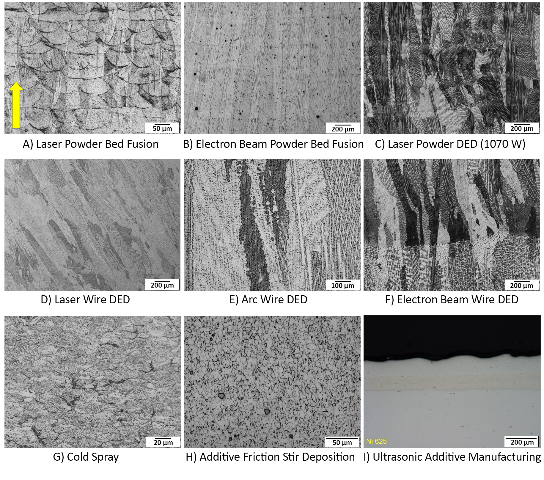
Fig. 5 As-built microstructure of Inconel 625 for the different metal AM processes with build direction (Z) noted by the arrow for all processes. Microstructures from A thru G based on (Ref); Image H for AFS-D adopted from (Ref). Image I courtesy of Fabrisonic. Note: Scales vary to provide the best definition of the as-built microstructure.
Summary
The end-use performance is the culmination of the proper design for AM; process inputs, control, and repeatability; and metallurgical characteristics. Even with the rapid maturity and industrialization of AM into aerospace applications, there are still unique lessons learned for each part and a proper path toward qualification and production. Ultimately, performance will require careful attention to each of the lifecycle steps to produce a part that meets metallurgical characteristics and properties, geometric tolerances and design intent, and an affordable path toward qualification for the part in service.
While AM processes encompass substantially more than may be documented in a single article, it is of paramount importance that future work continues to advance fundamental metallurgical characterizations and resulting properties, distill and disseminate academic research and industry results, analyze the benefits and drawbacks as AM processes mature, and ultimately provide a more holistic view for commercial aerospace applications.
Subscribe to Our Email Newsletter
Stay up-to-date on all the latest news from the 3D printing industry and receive information and offers from third party vendors.
Print Services
Upload your 3D Models and get them printed quickly and efficiently.


You May Also Like
3D Printing News Briefs, April 25, 2026: Competition Winners, AI Platform, X2D Printer, & More
In this weekend’s 3D Printing News Briefs, AMUG announced the winners of its Technical Competition, and Authentise launched AI platform Whisper at RAPID. Bambu Lab wasn’t at RAPID, but launched...
RAPID 2026: 6K Additive’s Domestic Metal Powders & Consolidation Plan
6K Additive (ASX: 6KA), a U.S. supplier and manufacturer of metal powders for additive manufacturing (AM), has been very busy lately. I caught up with CEO Frank Roberts and Chief...
3D Printing News Briefs, April 22, 2026: DINOs, Post-Processing, AM for Aerostructures, & More
We’ll start with event news in today’s 3D Printing News Briefs, as AMUG presented its DINO Award to six members at this year’s conference, and Axtra3D celebrated its five-year anniversary...
Medical, Electronics, & Semiconductors: Detailed 3D Prints at RAPID 2026 with Boston Micro Fabrication & Lithoz
They say that good things come in small packages, and that’s certainly the case when it comes to Boston Micro Fabrication (BMF). A leader in micro-precision additive manufacturing, the company...