
3D Printing Isogrid Structures with Carbon Fiber-Reinforced Polyamide

Because they feature high-performance qualities like the ability to withstand high temperatures, composite materials are often used in the aerospace industry. Structures like propellant tanks could suffer premature failure because high axial compressive loads cause them to buckle, but composite stiffening ribs, built in attached equilateral triangles (isogrid structures), can help keep them stiff and strong.
A type of partially hollowed-out design, isogrid structures are related to sandwich-structured composite panels, and NASA researchers first investigated them in the 1970s. Now, a team of Italian researchers from the Università Politecnica delle Marche and Università eCampus have published a paper, “Manufacturing Isogrid Composite Structures by 3D Printing,” that delves further into the subject.
For isogrid panels to help reduce buckling, the structures need to be optimized in order to, as the researchers explain, “maximize specific strength and stiffness.” For instance, “Jadhav et al. [7] optimized skin thickness, rib width and thickness and center-to-center distance between rib” to maximize energy absorption, and Zheng et al. [8] “suggested that the rib thickness should be larger than that rib width one due to the quadratic trend between critical force and thickness.”
“Isogrid structures were initially made of aluminum and were obtained by mechanical or chemical milling processes [4]. The improvement in the Automated Tape Laying (ATL) and Automated Fiber Placement (AFP) technologies has allowed the manufacturing of isogrid structures in carbon fiber reinforced plastics (CFRP) [9],” the researchers explained.
FFF is the preferred 3D printing method when it comes to fabricating fiber-reinforced materials, but little research exists regarding 3D-printed composite isogrid structures.
“In this framework, the present investigation aims at studying the feasibility of 3D printing production method for manufacturing of high performance isogrid panels in short fiber reinforced polyamide,” they wrote.
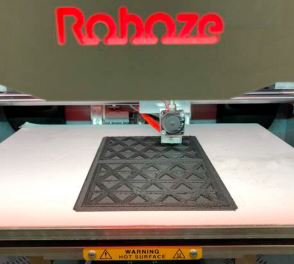
Fig. 1. The Roboze One+400 3D printer used for isogrid production.
The research team used the professional Roboze One+400 FFF 3D printer to build isogrid structures out of CarbonPA, “a polyamide reinforced with 20% [wt] of short carbon fibers” that can match the mechanical strength of aluminum alloys. They used a 0.6 mm nozzle diameter, and the material was dried ahead of time to remove any absorbed humidity.
“Then, during the printing process, the spool was kept at 70°C. The extrusion was performed at 240°C, with an infill density equal to 100%. After 2 hours since printing, the isogrid panels were weighted,” the researchers wrote.
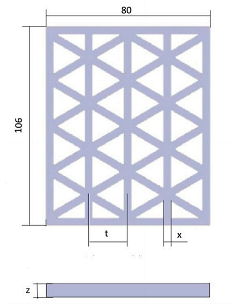
Fig. 2. Size and geometric variables of a typical isogrid panel with cell height equal to 24 mm.
Longitudinal ribs, oriented at 60° and 120°, were used to obtain isogrid panels, but the structure’s single cell “was constituted by an equilateral triangle.”
“Different values of the rib width (x) and cell height (t) were investigated, whilst, at this stage of the work, the rib thickness (z) was kept constant and equal to 4 mm,” they explained. “For each panel, the size of the sides parallel and perpendicular to the longitudinal ribs were kept constant and equal to 106 and 80 mm, respectively.”
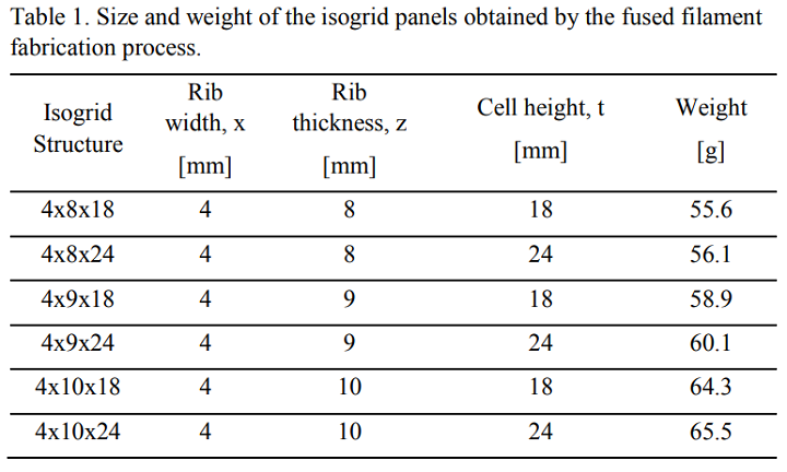
They used room temperature compression tests to investigate the “effect of geometric parameters, in terms of rib thickness and cell height, on the compressive strength and buckling behavior of the isogrid panels.” The panels were tested with a load capacity of 250 KN, on the universal MTS 810 testing machine, with a head displacement rate equal to 0.5 mm/min.
“During testing, the compressive load and platen displacement were acquired,” the team stated.
Fig. 3. Compression test of an isogrid structure in short fiber reinforced
polyamide.
The researchers analyzed the isogrid panel after the tests, and found that “failure occurs owing to the global buckling failure mode characterized by instability that extends to the whole structure.”
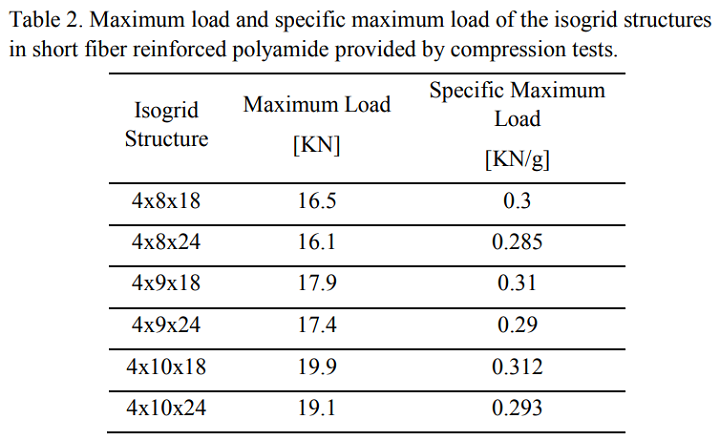
“It was shown that the specific maximum compressive load at the onset of buckling increases with rib thickness,” they wrote.
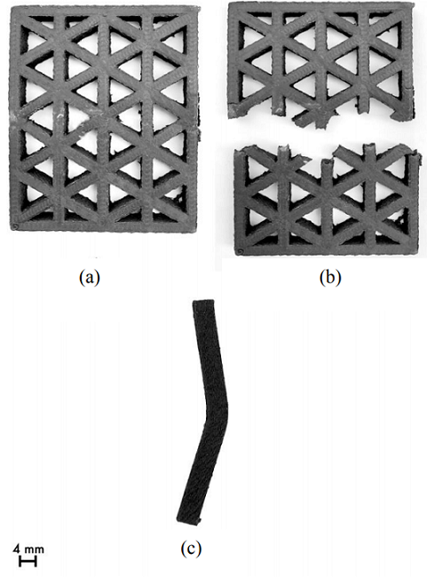
Fig. 4. (a) Front view of undeformed isogrid structure, (b) front view of isogrid structure after compression test; (c) side view of isogrid structure after compression test.
The below images shows the fracture resulting from the global buckling failure, which likely results from the structure slenderness being higher than the ribs.

Fig. 5. Typical fractured isogrid panel at a nodal intersection (4 x 10 x 18).
“Furthermore, the isogrid panel characterized by the lowest cell height exhibits the highest specific maximum compressive load,” the researchers explained.
“It can be seen that, irrespective of the isogrid size, load increases with displacement until reaching a peak value corresponding to the onset of buckling failure mode; then, due to the occurrence of buckling, load decreases until fracture of the isogrid structure.”
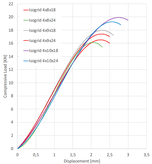
Fig. 6. Effect of the rib thickness and cell height on the compressive load vs. displacement curve of isogrid panels.
Finally, it seems that regardless of cell height, when the rib thickness rises, so too does the specific maximum load, which you can see below.
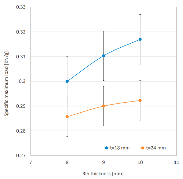
Fig. 7. Specific maximum load vs. rib thickness at different cell heights.
The team summarized its results by stating that:
- during isogrid panel compression tests, applied load rises with displacement and then decreases until fracture due to buckling;
- cell height increase results in maximum load and specific maximum load decreasing, while rib width increase leads to greater peak load and specific maximum load; and
- isogrid panel failure during compression tests results from global buckling failure mode, which demonstrates that the structure’s slenderness is higher than that of the ribs.
Discuss this and other 3D printing topics at 3DPrintBoard.com or share your thoughts in the comments below.
Subscribe to Our Email Newsletter
Stay up-to-date on all the latest news from the 3D printing industry and receive information and offers from third party vendors.
Print Services
Upload your 3D Models and get them printed quickly and efficiently.


You May Also Like
3D Printing News Briefs, July 2, 2025: Copper Alloys, Defense Manufacturing, & More
We’re starting off with metals in today’s 3D Printing News Briefs, as Farsoon has unveiled a large-scale AM solution for copper alloys, and Meltio used its wire-laser metal solution to...
Etsy Design Rule Change Reduces Selection of 3D Printed Goods
Online marketplace Etsy has implemented a rule change requiring all 3D printed goods on the site to be original designs. The update to the site’s Creativity Standards states, ¨Items produced using...
Siraya Tech Introduces New Elastomer 3D Printing Materials, Including Foaming TPU
California company Siraya Tech, founded in 2019 with a focus on material science, customer focus, and agility, develops high-quality 3D printing materials that meet the needs of creators, hobbyists, and...
3D Printing News Briefs, April 12, 2025: RAPID Roundup
The news from last week’s RAPID+TCT in Detroit just keeps on coming! That’s why today’s 3D Printing News Briefs is another RAPID Roundup of more exciting announcements from the trade...