

Predicting Mechanical Properties Based on Slimness Ratio in 3D Printed Samples


Engineers from the US and Brazil delve further into the complexities of mechanical properties in 3D printing, outlining their findings in the recently published ‘A highly accurate methodology for the prediction and correlation of mechanical properties based on the slimness ratio of additively manufactured tensile test specimens.’
3D printing and additive manufacturing processes continue to make significant impacts in a wide range of industries around the world; however, the more that users begin to rely on such technology and expand regarding innovation and project requirements, greater scrutiny is placed on mechanical properties—whether in regard to shape memory polymers, composite materials, or the effects of details like build orientation. The authors point out that industries like medicine, aerospace, automotive, and more are structured with strict regulations—leaving little room for error in critical applications.
As committees and standards within AM processes are called for, specific efforts are now geared toward:
- Classification of new guidelines
- Creating file formats for production of parts
- Development of criteria for technical reports
- General requirements for raw materials
There are still areas lacking required standards, however, such as mechanical characterization of parts. The researchers focus on popular new alloys being used such as Ti–6Al–4, now being used in a variety of AM methods, to include hybrid processes. Tensile testing can be used to assess:
- Yield stress (YS)
- Ultimate tensile strength (UTS)
- Elastic modulus €
- Uniform elongation (Elu)
- Elongation at fracture (Elf)
- Modulus of resilience (Ur)
- Tensile toughness (Ut)
- Reduction of area (RA)
The authors report that Ti–6Al–4V specimens offered a variety of mechanical property values, as follows.
- PBF with laser beam – YS values ranging between 684.3 and 1320.0 MPa, UTS from 480.5 to 1420.0 MPa, and Elf from 1.0 to 24.0%.
- DED specimens – tensile properties of YS from 522.0 to 1105.0 MPa, UTS from 716.0 to 1163.0 MPa, and Elf ranging 1.4 to 18.7%.
- WAAM process – mechanical properties from YS 800 to 884 MPa, UTS from 887 to 995 MPa, and Elf from 0.5 to 16.5%.
- Electron beam melting (EBM) – values of YS, UTS, and Elf ranging from 460 to 1150 MPa, 480 to 1200 MPa, and 1.5 to 25.0%, respectively.
“One of the most important parameters in tensile specimen geometry that directly interferes with the way Elf is measured and which is often neglected by various researchers is the slimness ratio,” stated the researchers.
Other studies have been performed, with a focus on the effects of slimness ratio in tensile specimens; however, the researchers noted both ‘disparity and lack of consensus’ in data in previous literature—leaving them to create a new technique for predicting mechanical properties.
The authors created several Ti–6Al–4V ELI (extra-low interstitial) tensile test specimens for the study. Four samples were made for each nominal slimness ratio, displaying varying lengths in gauge, with reduced area cross sections.
The samples were fabricated in one EBM batch, with the longitudinal symmetric axis parallel to the build platform, in the powder rake arm direction. Support structures were either milled in square/rectangle cross sections or turned in circular cross sections.
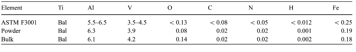
Chemical composition (wt%) of the Ti–6Al–4V ELI powder (ASTM F3001 [55]) determined from the ASTM standards: E1941 [56], E1409 [57], E1447 [58], and E2371 [59]
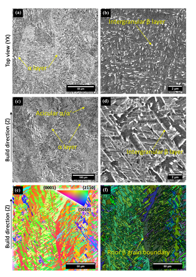
Microstructural characterization of the as-built Ti–6Al–4V ELI parts additively manufactured (AM) by EBM. VLM (a, c) and SEM-SEI (b, d) images from the top view (a, b) and build direction (c, d), respectively. EBSD maps exhibiting IPF along the build direction (e) and Euler angles (f).

a Representative engineering stress versus strain curves obtained from tensile tests of the specimens in the as-built condition. Crosssection notation means the initial nominal dimensions of the reduced section of the specimen and L0, the initial gauge length before the test. b Representative macroscopic image from the tensile test specimens after the tests (dimensions in mm).
Twelve different samples were tested as the authors investigated how the slimness ratio, k, affects the mechanical properties obtained from the stress versus strain curves.
“This concise set of specimens shows how difficult it is to analyze and compare the experimental data of tensile tests with different geometries,” stated the researchers. “Since one of the most important mechanical properties employed to verify the quality of the build parts is elongation, data dispersion makes this analysis very complicated.”

Average experimental and literature data of the elongation at fracture Elf obtained from tensile tests and plotted versus slimness ratio k. The dashed horizontal lines correspond to the minimum elongation values for the as-built* and heattreated** (e.g., stress relief, annealing, or HIP) according to AM standards. Ti–6Al–4V ELI specimens.
In examining strength properties YS and UTS, the researchers noted superior mechanical strength in the symmetric specimens.
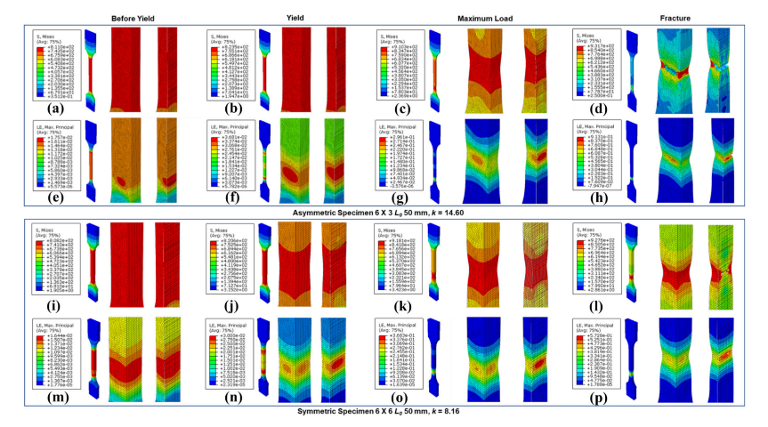
FE tensile specimens with asymmetric (a–h) and symmetric (i–p) cross sections. Von Mises stress and logarithmic strain contour profiles immediately before and at yield, at maximum load, and at fracture. Each item corresponds to a set of three images that correspond to an overview, a detailed image, and a longitudinal section view of the detailed image (from left to right).
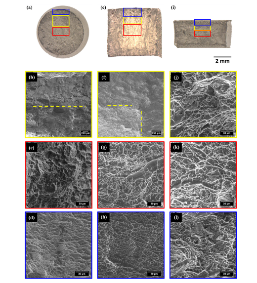
Representative low-magnification and SEM-SEI fractographies of the different cross-section specimens after tensile tests. a–d Ø 10 mm, e–h 6 9 6 mm, and i–l 6 9 3 mm. The color borders of the b–d, f–h, and j–l images correspond to SEM-SEI from the regions highlighted with rectangular marks (red center, blue edges, and yellow interface between them) in the fracture surface images (a, e, i)
“Circular and square cross-section specimens showed superior mechanical strength with similar mechanical behavior to high-stress-triaxiality parts subjected to tensile tests,” concluded the researchers. “A complex diffuse initial stress state favors yielding while symmetrical radial strain distribution favors increased stress triaxiality and consequently constrains plastic deformation and increases the maximum load.
“Fracture mode and micro-mechanisms of fracture are strongly influenced by the width/thickness ratio. Symmetrical specimens showed ductile cup-and-cone fractures and marked transition zones could be observed at the surface. The central region of the sample failed due to nucleation and the growth of voids in the tensile direction, while the periphery showed elongated dimples in the direction of higher shear stress. In very thin samples, the plane-stress condition applies, and no transition zones were observed with shear lip as the predominant failure mechanism.”
What do you think of this news? Let us know your thoughts! Join the discussion of this and other 3D printing topics at 3DPrintBoard.com.
[Source / Images: ‘A highly accurate methodology for the prediction and correlation of mechanical properties based on the slimness ratio of additively manufactured tensile test specimens’]Subscribe to Our Email Newsletter
Stay up-to-date on all the latest news from the 3D printing industry and receive information and offers from third party vendors.
Print Services
Upload your 3D Models and get them printed quickly and efficiently.


You May Also Like
Divergent Declares that German 3D Printers are Superior, And Plans Massive LPBF Expansion
Divergent has announced a new version of its Laser Powder Bed Fusion (LPBF) printer and a new site. The company aims to do nothing short of “further accelerating its mission...
Incodema3D Buys 14 Metal EOS Systems, Now One of the World’s Largest Metal 3D Printer Operators
Recently, a majority stake of 3D printing service bureau Incodema3D was purchased by AFM Capital. Under new ownership, the Freeville, New York company is now using its cash-rich parent for...
CEO Yoav Zeif on Why Stratasys’ Markforged Acquisition Is Really a Bet on Industrialization
When Stratasys announced plans to acquire Markforged, the immediate focus was on the deal. Markforged is one of the most recognizable names in additive manufacturing (AM), known for its continuous...
3D Printing & the Autonomous Era: Defense Tech’s Latest Mutation
When we last checked in on the broad defense tech landscape and the role of the additive manufacturing (AM) industry in that environment, it became clear that the connecting thread...