Binder Jet Processing: What Happens After Printing? A Review of Key Process Steps & Design Considerations


Author(s): Kirk Rogers & John Barnes
In our previous article, we covered design considerations for Binder Jet Processing (BJP) by highlighting the critical process steps which also form design constraints. In this article, we take a deeper dive into the details of de-binding and sintering.
Two powder particles walk into a binder jetting bar. The first says it is looking for some capillary action. The second says it is saturated from the impact of his joke. Later, when they were caught necking, they blamed it on the diffusion of the potent liquid binder they’d been served and didn’t appreciate being made the sinter of attention. Yes, we just made a binder jetting joke. However, the art and science of processing in binder jet processing is no laughing matter. In fact, it is the diffusion of that matter that makes it a solid part of our article.
Previously we introduced the concepts of de-binding and the 3 stages of sintering and key MfAM (Modify for AM) and DfAM (Design for AM) implications. Now we will concentrate on the thermal processing required to achieve density and therefore mechanical properties for the part. The thermal process includes two key, and quite different, thermally driven events: de-binding and sintering. Figure 1 shows the progression of treatments applied in steps, or over time, beginning with two steps associated with de-binding and three steps associated with sintering. The green line denotes the transition from de-bind to the initial stages of sintering.
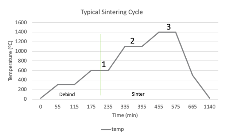
Figure 1: De-bind and sinter cycle for a steel with elapsed time and temperature.
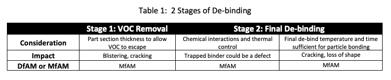
De-binding can be divided into two distinct steps:
De-bind 1 – Remove any water and volatile organic components (VOCs) of the binder, shown here at 300°C (572°F).
De-bind 2 – Remove or “burn out” the binder, typically between 400 and 600°C (750-1100°F).
During De-bind 2, the temperature is just hot enough to begin the early stages of sintering. Selection of the final de-bind temperature and time is critical. It is in this phase where the part transitions from being held together by the binder, which is being removed, to being held together by powder particle to powder particle bonding. Considerations and impacts of the two stages are detailed in Table 1.
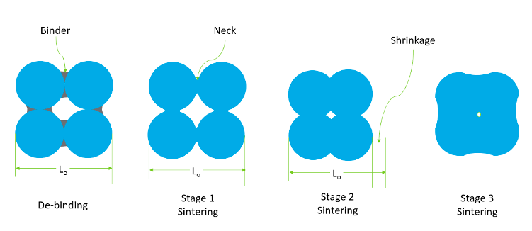 Sintering can be broken into three distinct steps which are illustrated in Figure 2.
Figure 2 – 2-dimensional view of de-binding and sintering from a particle perspective.Sinter 1 – Also known as the neck growth stage, particle to particle contacts broaden from point contacts to forming a fatter connection called a neck. During this stage there is little change in dimensions observed.
Sinter 2 – The intermediate stage of sintering starts when the adjacent necks between particles begin to impinge on each other. During this stage, the open spaces between powder particles become smoother cylinders, and a growing solid mass will pinch off a smaller cylinder, resulting in a trapped pore. During this stage, the entire body shrinks, up to 15-20% by volume.
Sinter 3 – The final stage of sintering begins when most of the pores are closed. Material has to move into the pores left by the second stage and the gas that is in the pore must escape by diffusion through the solid. Some shrinkage occurs but not comparable to Sinter 2. Staying at stage 3 may seem appealing but left behind compressed gas trapped in the solid can later expand creating larger pores.
Shrinkage is an important topic in a sintering driven process like binder jetting, because it causes the volume of the desired part to shift or distort. Failure to account for shrinkage would lead to not hitting the dimensions of the part, for example. Shrinkage happens by a process called diffusion, wherein the atom in a solid moves due to a gradient in external force and temperature. The force comes from the reduction in surface area of the body. The sintering temperature is typically greater than 70% of the melting temperature in metals.
MfAM can be used to mitigate distortion, however there are many design factors to take on board:
- Thick features shrink more than thin features creating non-uniform distortion.
- Abrupt changes in section thickness can result in surface cracks due to the differences in shrinkage.
- Gravity causes large openings and overhangs to distort.
- Contact with the sintering tray creates drag causing the bottom of the part to shrink less than the top.
Table 2 lists additional possible defects typically created by lack of MfAM. Figure 3 shows examples of sintering defects: surface crack, distortion, and binder blow out.
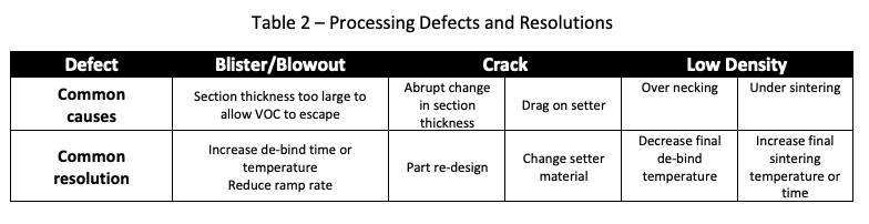
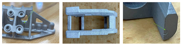
Figure 3 – Sintering defects: Large surface crack, distortion, binder blowout (images courtesy of FreeFORM Technologies)
Hopefully, by appreciating the de-binding and sintering mechanisms, the design process can be modified to help achieve design for AM success sooner than later. We hope to diffuse this information to you creating the smallest amount of stress. Binder jetting and related AM technologies will continue to increase in relevance in manufacturing, and it is our hope to provide some tips to make that transition easier and faster.
Subscribe to Our Email Newsletter
Stay up-to-date on all the latest news from the 3D printing industry and receive information and offers from third party vendors.
Print Services
Upload your 3D Models and get them printed quickly and efficiently.


You May Also Like
Beyond Thermoplastics: Why JuggerBot Is Betting on Hybrid AM
For years, thermoplastics have been the workhorse of additive manufacturing (AM). They are pretty easy to process, available, and compatible with many of today’s industrial 3D printers. From prototypes to...
RIC Robotics Collaborates with K4k Construction on 3D Printed ADU in Sacramento
In 2024, RIC Robotics, the additive construction (AC) firm based in Denver, completed the build of an accessory dwelling unit (ADU) in Walnut, California, which was apparently an industry first....
Printing Money Episode 40: 3DP/AM Deal Analysis and More with Matthias Schmidt-Lehr, AMPOWER
Welcome to Printing Money Episode 40. Matthias Schmidt-Lehr (AMPOWER, Executive Partner) joins Danny for this episode and we are very thankful to have him back. In Episode 40, Danny and...
Additive Manufacturing at a Crossroads
Additive manufacturing is at a crossroads. Simultaneously, we find ourselves between certain very different modalities, applications, and industries. Rather than being able to explore them all, companies will now have...