Scale Modeling Tutorials: 3D Modeling Basics for 3D Printing


In my last article, I discussed the use of 3D printing for scale model hobbyists. Hobbyists are discovering 3D printing to be a useful tool to make customized parts, or even create detailed models from scratch and shared a few of my own 3D printed models. 3D modeling may seem daunting to many 3D printing hobbyists, but the learning curve isn’t as steep as many think and there has never been a better time to start learning. It’s fun to browse sites like Thingiverse for free models, but there’s a certain satisfaction that comes from printing something you designed yourself. If you’re interested in making your own models, I’m here to help with everything you need to get started.
I will be sharing more hobby-related tutorials in the future, including more detailed modeling walkthroughs, the best settings for printed models and how to finish and paint your prints. For now though, let’s jump into the basics of CAD design.
CAD, or Computer Aided Design, is any computer software used to create, modify or optimize designs. It has a wide range of applications, from concept design, to machining and manufacturing and, of course, 3D printing! There are a number of CAD options available today, ranging in price from free to outrageously expensive. Fortunately, hobbyists today don’t have to compromise on quality and functionality when opting for free options. My personal favorite is Fusion 360 and this article will focus on teaching you everything you need to start making your own models with the software.
Autodesk’s Fusion 360 is a powerful, cloud-based CAD software that offers a number of features. It’s also free for non-commercial use! Non-commercial use, in this case, means anyone making less than $100,000 per year using the software. This makes Fusion 360 the perfect option for hobbyists looking to make their own models.
Getting Started
Fusion 360 can be downloaded from Autodesk’s website and choosing the non-commercial/personal download option and following the download instructions. After creating an Autodesk account and following the download instructions, Fusion 360 is yours to play around with!
Navigating Fusion 360:
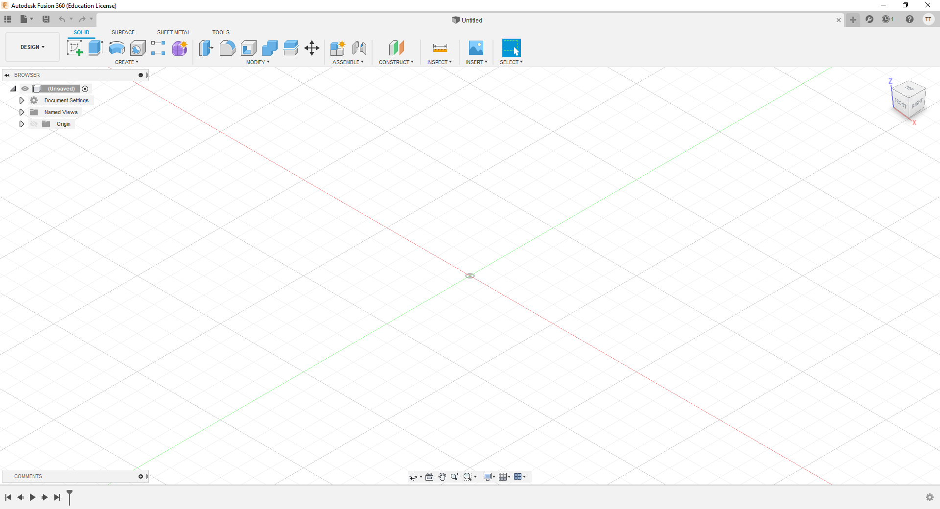
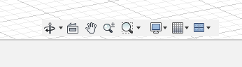
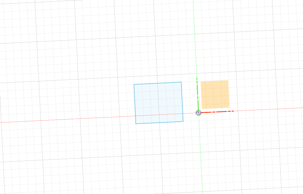
When you first open Fusion 360m you’ll see an empty workspace with three planes highlighted on the X, Y and Z axes. This is where we’ll be drawing out sketches and creating objects (more on that later). Note: if you don’t see a grid when you first open the program, navigate to the “Grid and Snaps” settings at the bottom (the icon that looks like a grid), clicking the dropdown arrow and checking “Layout Grid”.
The first thing you need to know is how to move around in the workspace. Use your mouse wheel to zoom in and out. Pressing down on the mouse wheel and moving your mouse will allow you to pan back and forth. Holding shift and the mouse wheel and moving your mouse will allow you to orbit around the scene. You can also select different camera angles by clicking on different axes (X, Y and Z) or views (Back, Front, Top, etc.) in the top right.
Views and navigation in Fusion 360 can be customized in the selection box at the bottom. In the orbit settings, I prefer “Constrained Orbit”, which makes the environment easier to navigate. As mentioned before, I like to include the layout grid in the “Grid and Snaps” settings, but that can be unchecked if need be. I prefer the default settings for everything else.
Basic Overview of the Workspace
Now that you know how to move around in Fusion 360, let’s go over some of the basic functions and where to find them. Clicking the “Show Data Panel” box in the top left will bring up a list of your recent designs. If you’ve just opened Fusion 360 for the first time, this should be empty. Clicking the “File” dropdown right next to it will bring up the basic options you’d expect, like opening a new file, saving and exporting designs (as an STL, OBJ, etc.). There’s also a quick-save icon next to that.
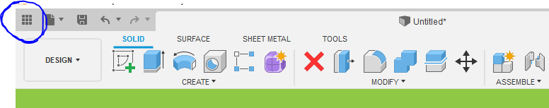
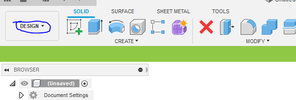
Directly below those options you’ll find a Workspace dropdown, allowing you to select a design environment. You’ll find a number of environments, including Design, Render, Animation, Simulation, Manufacture and Drawing. The default should be set to Design, the workspace in which we will create our design using sketches and objects. I may dive into the other workspaces in future tutorials, but the Design environment is all you will need to start making your own models.
To the right of the Workspace dropdown you’ll find the main design ribbon, with four tabs (Solid, Surface, Sheet Metal and Tools). We will be focusing on the Solid tab, so click on that if it’s not already selected by default. This ribbon contains all the tools we need to start creating so let’s start with the most basic tools you’ll need to start off with.
The CAD Design Process
There are really only two things you need to know how to do to start modeling:
- Create a two-dimensional sketch
- Do something to it
“Do something” can mean a number of actions (extruding, revolving, lofting, etc.), but that’s the basic process and really the steps you’ll follow to start creating models. Before we jump into an actual example, though, let’s go over the basic components and functions of CAD design.
Point: a precise location on a plane, represented by a single dot
Edge/Line: The distance between two points
Face: A flat surface formed by the intersection of three or more lines
Plane: a flat surface formed by the intersection of two axes or lines
Sketch: a two-dimensional drawing
Object: a three-dimensional shape
Creating an Object
Now for the fun part! Let’s use that information and the basic functions in Fusion 360 to create a basic, three-dimensional object. Following our two basic steps, we’re going to: 1. Create a sketch, and 2. Do something to that sketch—in this case extrude it.
Creating a Sketch
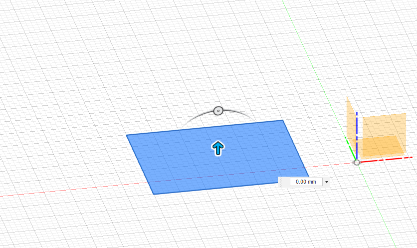
To create a sketch, navigate to the ribbon at the top and click “Create Sketch”. Of course, the sketch needs to be created somewhere, either on a plane or a face, so click the XY plane at the center of the workspace (the yellow square formed at the intersection of the X and Y axes). The camera should now jump to a view directly above the plane you selected. You will also notice a new “Sketch” tab at the top and several new options to choose from. From the “Create” dropdown, select “Rectangle”, then “Two Point Rectangle”. This will allow us to draw a basic rectangle. Click anywhere on the workspace to place the first point of the rectangle. Next, move your mouse until your rectangle is the desired size. Now, just click and you’ll notice the rectangle turn blue. Congratulations! You’ve just created your first sketch!
A Quick Note on Hotkeys
Eventually, you will want to learn some of the basic hotkeys in Fusion 360. Instead of clicking the “Create Sketch” button and selecting Rectangle, typing the “R” key will automatically create a new sketch and allow you to start drawing a new rectangle. Similarly, typing “C” will create a new sketch and allow you to draw a circle.
Doing Something to Our Sketch
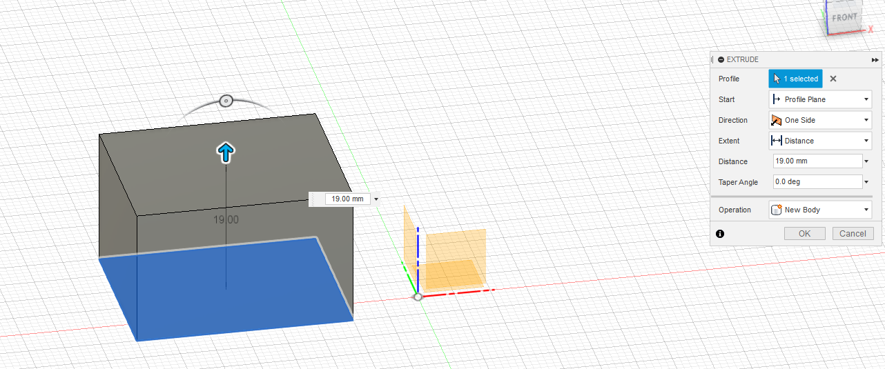
Now, it’s time to “do something” to our sketch. In this case, we will be extruding the sketch, which basically means turning a 2D sketch into a 3D object. First, click “Finish Sketch” in the top right. You should now see the “Solid” tab from before. Click the “Create” dropdown and select “Extrude” (or just type “E”). Now, click the sketch we just created, which will highlight the rectangle in a darker blue. In some cases, Fusion 360 will automatically select the last sketch you created. You’ll notice an arrow over your sketch. Click and hold the arrow, and drag it up. When you like the height of your extrusion, simply click “Ok” on the Extrude window. Congratulations! You’ve just created your first 3D object! Now, let’s repeat those steps and build on our object.
Taking it Further
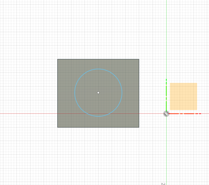
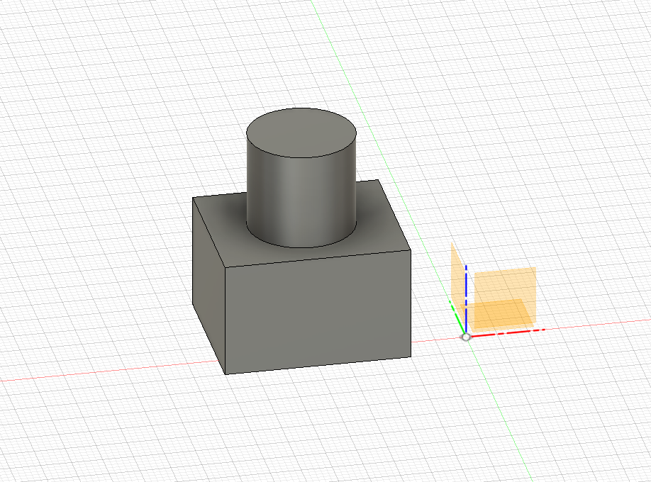
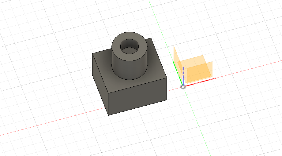
Let’s keep making sketches and manipulating them to showcase some of Fusion 360’s other functions. Of course, a sketch can be created on a surface. So, let’s add a cylinder on top of our box. Create a circle by typing “C” (it’s never too early to learn the hotkeys) and click on the top face of the box. Now, click somewhere in the middle of the top face to place the circles center point. Then move your mouse to draw out your circle and click to create the sketch. Next type “E” to extrude. Click the circle and extrude the circle as we previously did with the rectangle. There are a few options available in the “Extrude” window before clicking ok. For now, focus on the “Operation” dropdown. Selecting “Join” will join the current object. Selecting “New Body” will create a new object that can be moved separately from the box below it. Let’s just join them for now and click ok.
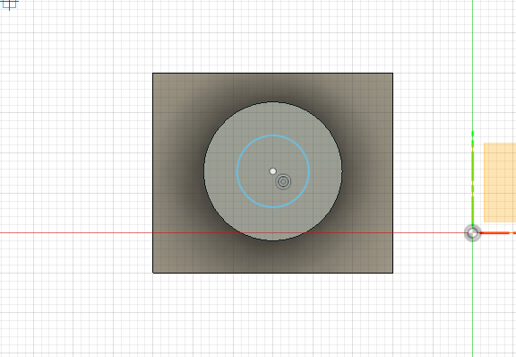
Let’s draw another circle on the top of our cylinder. Type “C” and click the top of the Cylinder. Create a sketch as we did before. Type “E” to extrude and click the circle just as before. This time, however, drag the sketch down, instead of up. You will notice the new shape is now red and the “Operation” in the Extrude window is set to “Cut”. Instead of creating a new shape, we’re now cutting geometry out of the existing shape. Click “OK” in the Extrude window.
Stay tuned, because this is just the beginning. In the second half of this tutorial, we’ll be expanding on what we’ve learned so far to create a simple fuel canister for a spacecraft. If you enjoyed this tutorial and want to see some of my models, check out my Instagram, where I share pictures of my designs and prints as well as painting tips.
Subscribe to Our Email Newsletter
Stay up-to-date on all the latest news from the 3D printing industry and receive information and offers from third party vendors.
Print Services
Upload your 3D Models and get them printed quickly and efficiently.


You May Also Like
3DPOD 302: Digital Inventory for AM with Mikhail Gladkikh, Würth Additive Group
Mikhail Gladkikh has worked in oil and gas for many years. With this background, we obviously talk about energy market turbulence and the adoption of AM in oil and gas....
Spectrum Filaments Gets Investment: How They Could Win in Filament
Spectrum Filaments is a long-time high-quality filament supplier based in Poland. With good tolerances, roundness, and consistency coupled with affordable pricing, the firm has been a mainstay for makers, industrial...
NX Atomics and Sciaky Collaborating to 3D Print Nuclear Components
For decades, the nuclear industry has quietly experimented with and implemented additive. Bouyed by the likes of ORNL, companies such as Westinghouse have 3D printed components serially. We have an...
Incodema3D Buys 14 Metal EOS Systems, Now One of the World’s Largest Metal 3D Printer Operators
Recently, a majority stake of 3D printing service bureau Incodema3D was purchased by AFM Capital. Under new ownership, the Freeville, New York company is now using its cash-rich parent for...