What is Metrology Part 21 – Getting Started with Processing


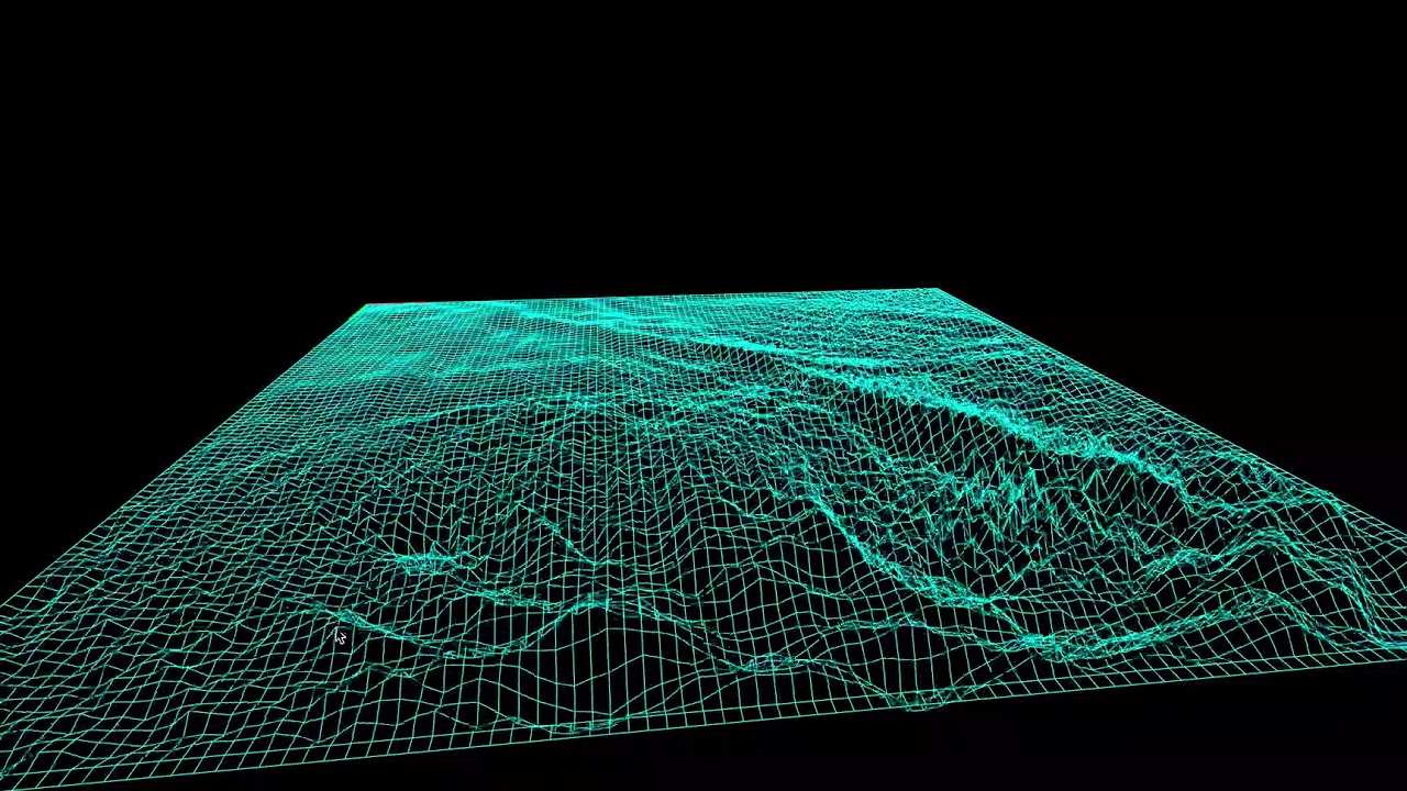
3D Environment Simulation in Processing
In the previous article, I showed the awesome coding framework of Processing. It is fun and interactive for anyone new to code. It makes learning a simple breeze, and it lines up a lot with the topics we have covered within this series thus far. These topics include image processing, 3D image rendering, 3D scanning, pixelation, image restoration, and a slew of other applications. With this article, I will show you how to get started with this program.
To get started, one should visit Processing and their website. From there, you can go to their downloads page and find the corresponding installation package that is right for your system. The package for Processing will be found in a zip file in your downloads section once it is unpacked from the website. Within this download package you will click through it to find an icon that says processing. Once you click this your computer will prompt you to extract the file into a different location. After this you may now use Processing.
Once you open Processing you will notice the sketchbook and developing environment. That is where all of the code will be run and executed. In order to code within this environment, one needs to understand how to manipulate movement and vision within the 2D realm first before moving to 3D. I think having a solid foundation within 2D leads to better 3D thinking because geometry naturally flows this way. Processing is object oriented and it utilizes rotational and translational commands to make interesting visuals. The majority of commands used in 2D will be applicable to 3D. Processing fortunately has a 2D transformation tutorial online that is a great starting point for explaining the capabilities. Below is a snippet of code that is from the processing site and it has comments on what these lines mean.
void setup(){

  size(200,200); //size of the window

  background(255); //color value of the background

  noStroke(); //disables the border drawing of the stroke

  //draw the original position in gray

  fill(192); //Sets the color used to fill shapes.

  rect(20, 20, 40, 40); //draws the rectangle with these dimensions

  //draw a translucent blue rectangle by translating the grid

  fill(0, 0, 255, 128); //fills a rectangle with the blue color

  pushMatrix(); // Pushes the current transformation matrix onto the matrix stack.

  translate(60, 80); //translates the original rectangle 60 units right and 80 units down

  rect(20, 20, 40, 40); //draws the location of the translated data of the original matrix

  popMatrix(); //  Pops the current transformation matrix off the matrix stack.

}
To initialize a build environment in Processing, one needs to setup the environment. Setup calls a function for a viewport to see the digital code. The window size is denoted as well as the background color. The noStroke() function disables Processing and its automatic border drawing for images.
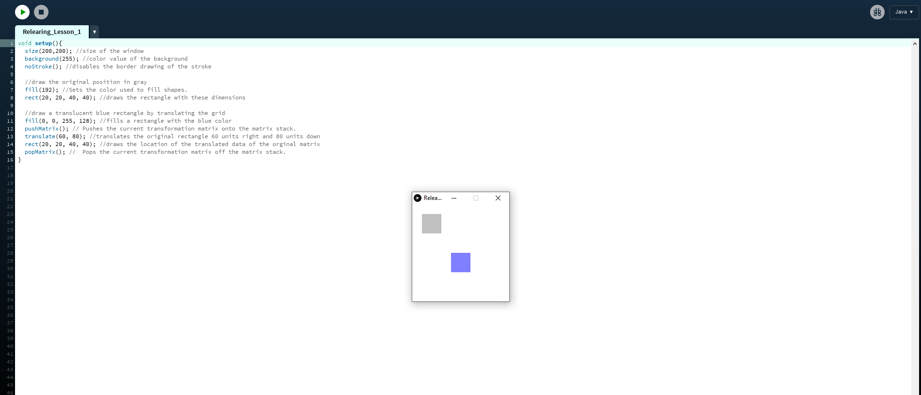
Executed Script in Processing
Then a fill function is used to color any shape after this definition to be this color. To set the dimensions of our box, we used the rect() function. Then we wanted to create a new blue rectangle so we applied the fill function again but with different values. After this we want to apply translations to the original matrix data we had for the rectangle in terms of location. The pushMatrix() command essentially opens up a loop of interaction within our code to allow us to independently control objects within our environment. Then we are able to apply the translate function to our original matrix data. In this case we translated the data to the right 60 units and down 80 units. Then we ended this cycle by applying the command popMatrix().
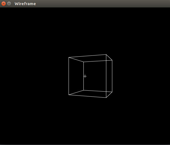
Whenever one wants to code, it is good practice to know what every command or function within your code means. Without knowledge of this, you are going to become a copy and paste coder who does not understand the nuances within their own code. It also will take you a bit more time to go through programming tutorials when you stop to learn exactly what everything means, but at a certain point you will gain a greater overall scope of the tools you have at your disposal. With this basic code example, we can expand our skills and apply this in 3D. In the next article, I will show how to do so.
Subscribe to Our Email Newsletter
Stay up-to-date on all the latest news from the 3D printing industry and receive information and offers from third party vendors.
Print Services
Upload your 3D Models and get them printed quickly and efficiently.


You May Also Like
The New Dental Lab: “Three Technicians Can Handle a Hundred Arches,” Says Digital Dentistry Expert Josh Jakson
Josh Jakson’s path into digital dentistry started long before he had a job title. He grew up around it. His father, a Polish immigrant, started the family’s dental laboratory in...
AM Asia Watch: China’s HeyGears Lands $44M to Expand Beyond Dental 3D Printing
Chinese 3D printing company HeyGears raised more than 300 million Yuan (roughly $44 million) in a new Series C funding round as it looks to expand beyond its industrial and...
Asia AM Watch: China’s SHINING 3D Restarts IPO Review Process
SHINING 3D is moving forward again with its plans to go public in China, after restarting its Beijing Stock Exchange (BSE) initial public offering (IPO) review process and filing updated...
3D Printing Financials: Align’s Growth Runs on Volume
Align Technology (Nasdaq: ALGN) kicked off 2026 with steady financial results, with most of the growth coming from its core high-volume 3D printing business. The maker of Invisalign reported first-quarter...