
Eliminating Porosity in Metal 3D Printing through Thermocapillary Force


In ‘Pore elimination mechanisms during 3D printing of metals,’ researchers from around the world explore more about refining laser powder bed fusion (LPBF) technology through the use of imaging and modeling techniques meant to prevent porosity.
While 3D printing with metal has become extremely popular, and especially within the industrial realm, there are still numerous challenges to overcome before many users are able to completely embrace such processes. In this research, the authors use in-situ high-speed high-resolution synchrotron x-ray imaging and multi-physics modeling to understand more about how to control porosity issues as they so often occur in the melt pool and are then found in parts.
It is often difficult for users to take measures to reduce porosity through post-processing:
“For example, the hot isostatic pressing (HIP) cannot close the surface pores; and the gas pores closed by HIP can reopen and grow during subsequent heat treatment,” state the researchers, who began looking for the most logical route to fix the problem—during the printing process.
Pores exhibiting high velocity and small size make it hard for researchers to examine their motion while the printing process ensues. X-rays have been somewhat successful previously, but with inferior resolution. The research team discovered that pores move not only according to temperature and thermocapillary force, but also drag force caused by the melt flow. Further, they found that the high thermocapillary force could overcome the drag force, thus halting pores from forming during printing.

In-situ characterization of pore dynamics during LPBF process. a Schematic illustration of the in-situ high-speed X-ray imaging experiment. b Representative cuboid (300 µm × 200 µm × 200 µm) reconstructed from X-ray computed tomography data showing the size and distribution of pores inside an additively manufactured AlSi10Mg plate. c Representative single-pulse X-ray image revealing micro-pores as well as the melt pool and depression zone beneath the surface of the powder bed (laser power of 360 W, scan speed of 1 m s−1 and laser beam diameter (D4σ) of 100 μm). The boundaries of the melt pool and the depression zone are indicated by a white dashed line, and the position of the laser is indicated by a red arrow. The scale bar in c is 50 μm
In situ X-ray imaging consisted of the following:
- Powder bed system – 100 µm layer of powder on a substrate sandwiched between two glassy carbon plates
- Selective laser melting system (for scanning the powder bed and forming a melt pool)
- High-speed X-ray imaging system – showing the LPBF process
“To study the effect of thermocapillary force on pore dynamics in different locations of the entire melt pool, we developed a force map based on the ratio of thermocapillary force to drag force (Ft/Fd) for a 10 μm-dimeter pore, using the local temperature gradient and the average velocity of the melt flow (1.1 ± 0.5 m s−1). The buoyant force is neglected because it is orders of magnitude smaller than the thermocapillary force and the drag force for the pore size range studied here,” stated the researchers.
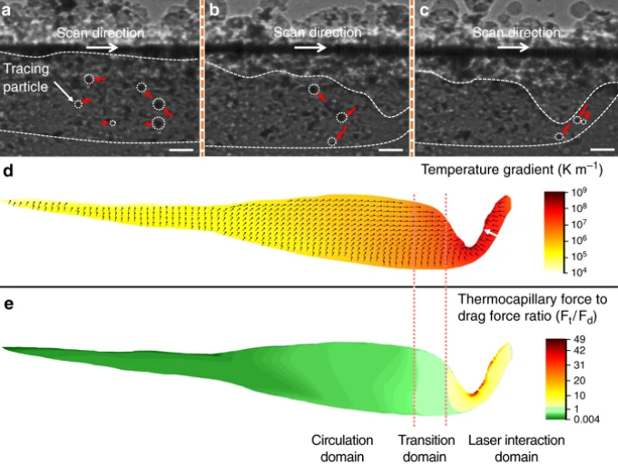
Driving forces for pore motion and elimination. a–c X-ray images showing trajectories (indicated by red arrows) of the tracing particles (tungsten microparticles, marked by white dotted circles), which indicate the melt flow at the circulation domain (a) transition domain (b) and laser interaction domain (c) inside the melt pool during the LPBF process. d Temperature gradient inside the melt pool during LPBF process, obtained by multi-physics modeling with laser processing parameters the same as the in-situ experiments (see “Methods” section). The magnitude and direction of temperature gradient are indicated by color and black arrows, respectively. The white arrow indicates the temperature gradient increases from the solid-liquid interface (melting front) to the depression zone front wall (Fig. 5). e Ratio of thermocapillary force (Ft) to drag force (Fd) for a pore with a diameter of 10 µm. In a–c, the laser power is 360 W, the scan speed is 1 m s−1 and the thickness of powder layer is 100 μm. Scale bars in a–c are 50 μm
Experiments were also performed to see how this process would affect 3D printing not driven by powder. The results showed ‘similar pore motion behaviors.’
Overall, the researchers found that they were able to use thermocapillary force to eliminate pores while LPBF was in progress. They demonstrated this during printing, as well as showing that pores in previous layers were eliminated by ‘thermocapillary force by laser rescanning with proper laser scan parameters.’
The researchers expect this study to have positive implications for applications like:
- Laser polishing
- Laser cladding
- Welding
- Melt spinning
- Nuclear reactors
- Chemical reactors
“We achieved pore elimination by thermocapillary force in both alloys, which indicates that the thermocapillary force driven pore elimination mechanism is not limited to a specific alloy system,” stated the researchers.
Porosity is an ongoing topic of research 3D printing users continue to refine manufacturing processes, and especially in metal—but also extrusion-based printing, FDM 3D printing, and in bioprinting too. What do you think of this news? Let us know your thoughts! Join the discussion of this and other 3D printing topics at 3DPrintBoard.com.
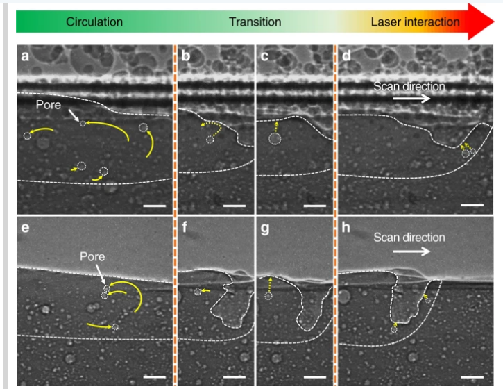
Dynamic pore motions within melt pool. a–d X-ray images showing pore dynamics during the LPBF process. The thickness of a powder layer is 100 μm. e–h X-ray images showing pore dynamics during laser melting of a bare substrate. Dotted arrows indicate the future trajectories of the pores, while solid arrows mark the history of pore trajectories. Pores follow circular patterns at the circulation domain (a, e), while pores in the laser interaction domain move toward depression zone and escape from the melt pool (d, h). In the transition domain (b, c, f and g), pores exhibit irregular moving behavior, sometimes moving toward the melt pool surface and escaping (c, g), and sometimes circulating in the melt pool (b, f). The laser beam diameter (D4σ) is 100 μm, the laser power is 360 W, and the scan speed is 1 m s−1. All scale bars are 50 μm
Subscribe to Our Email Newsletter
Stay up-to-date on all the latest news from the 3D printing industry and receive information and offers from third party vendors.
Print Services
Upload your 3D Models and get them printed quickly and efficiently.


You May Also Like
NASA Selects Relativity Space for Mars Science Mission
NASA has selected Relativity Space as its commercial partner for a new Mars science mission scheduled for launch in 2028, giving another boost to one of the most well-known additive...
Fabri Raises $13.5 Million to Create Digital Foundry
Fabri is a startup that wants to create a “digital foundry,” and just raised some funds to help it reach this goal. There are far too few foundries in America....
Limitless Labs Raises $20 Million in Series A Funding for Agentic CAD
Limitless Labs has raised an additional $20 million for its agentic CAD/CAM platform, bringing its total funding to date to $27.3 million. Investors in the Series A round include Dell...
The Seminal Moment: Creality’s IPO Analysis & Possible Effects
Something super important happened just a few days ago, and too few people paid attention. Creality, a pioneer in low-cost desktop material extrusion printers, went public. Creality is now listed...