
NIST Achieving Better Laser Powder Bed Fusion 3D Printing Melt Pool Control By Implementing Laser Control


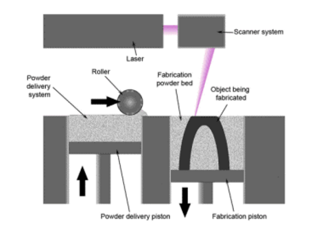
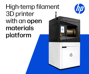
Diagram of laser powder bed fusion system. [Image: Andrew Drieling, Wright State University]
LPBF defects can occur when these laser parameters are combined incorrectly, and there has been research published on hypotheses like shaping laser beams to enhance properties and using the right heat source. But having better controlled power profiles or density along scan paths can lower the likelihood of defects forming.
![]() A team of researchers from the National Institute of Standards and Technology (NIST), which built an open architecture Additive Manufacturing Metrology Testbed (AMMT) for studying advanced process monitoring and control strategies, recently published a paper, titled “Implementation of Advanced Laser Control Strategies for Powder Bed Fusion Systems,” on their efforts to implement laser control on the AMMT in order to negate the formation of defects and achieve better melt pool control.
A team of researchers from the National Institute of Standards and Technology (NIST), which built an open architecture Additive Manufacturing Metrology Testbed (AMMT) for studying advanced process monitoring and control strategies, recently published a paper, titled “Implementation of Advanced Laser Control Strategies for Powder Bed Fusion Systems,” on their efforts to implement laser control on the AMMT in order to negate the formation of defects and achieve better melt pool control.
The abstract reads, “Laser path, scan speed, and laser power are critical machine parameters for determining the quality of the output of laser-based powder bed fusion (LPBF) processes. A jerk-limited control strategy is implemented for laser path planning on a LPBF additive manufacturing (AM) testbed. The actual and commanded laser paths/velocities are found to be in better agreement with each other compared to conventional controls. The new controller enabled implementation of advanced laser power control strategies synchronized with laser position and velocity by embedding all into a modified G-code (referred as AM G-code). An interpreter is developed to utilize sophisticated LPBF laser control commands.”
Comparison of jerk-limited and step velocity motion control at different speeds.
LPBF system laser control involves laser power and path: the former is electronically adjusted through the laser amplifier, while the latter is achieved by controlling the two galvanometer motors, which drive the mirrors that direct the laser spot to the powder bed, in a coordinated manner.
Step velocity, which assumes infinite acceleration, makes it impossible for the mirrors to follow commands, but most commercial scanning systems, including those integrated into LPBF 3D printers, use step velocity profiles for motion control. This compromises temporal and spatial accuracy, which then leads to material defects and geometric inaccuracies.
“In numerical control of machine tools, a jerk-limited path is usually used to avoid excitation of vibration modes in the mechanical structure,” the researchers wrote. “A jerk-limited path has a smooth velocity profile which is more easily followed by a physical system, and results in better spatial and temporal path accuracy. Here, spatial accuracy refers to geometric position of the laser spot, and temporal accuracy refers to the spot reaching designated positions at the designated time. Temporal accuracy is not usually a concern for machine tools. However, for advanced LPBF scan strategies incorporating line-to-line or within-line velocity or power control, both temporal and spatial accuracy are essential. To accomplish this, jerk-limited motion control is implemented on the NIST AMMT.”
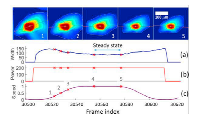
A single-track scan on stainless steel. (a) Melt-pool width (µm) measured from in-situ melt-pool images. (b) Commanded laser power (W). (c) Commanded laser speed (m/s). Melt-pool images corresponding to the marked locations (1-5) are shown on the top.
The researchers used varying motion control parameters to generate nine square laser scan paths on the AMMT. A wait time was introduced after each move with the step velocity profile, in order to “improve spatial path accuracy,” but it had to be carefully measured – too short, and the distortion can’t be fully compensated for, while waiting too long can cause over-melting.
“To visualize the effect of temporal path accuracy, two series of 2 mm x 2 mm patterns were scanned on an aluminum plate at different speeds (200 mm/s to 2000 mm/s) with jerk-limited and step velocity motion controls,” the researchers wrote.
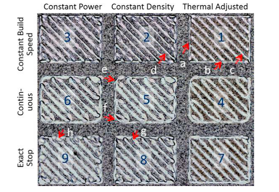
Path planned by the combinations of three laser path and three laser power modes. Image shows the scan on a stainless-steel plate.
Constant power modes and build speed were used to turn the laser power on and off at designated positions. Acceleration for jerk-limited control was set at 1,000 m/s2, while wait time for step velocity control was calibrated at 200 mm/s.
“The gaps in the scanned patterns for step velocity control indicate the laser spot did not reach the designated position at the designated time (i.e., a temporal error),” the researchers explained. “No gap was observed for jerk-limited control at all speeds.”
The input energy density was found to be influenced by laser power and scan speed, and errors could potentially cause material defects. The researchers also set up a high-speed camera to measure the melt-pool geometry, which can help when studying the influence that laser control has on LPBF.
It’s also possible to use jerk-limited path planning to create complicated scan strategies, and ensure a smoother build if the laser speed and power variations are reduced. So the researchers proposed the use of laser path and power modes, and put them to use through a modified version of G-code.
“A jerk-limited motion control was implemented on a LPBF AM testbed, and improved position and velocity temporal accuracies were demonstrated,” the researchers concluded. “This enabled the implementation of advanced laser control strategies based on precise power-velocity-position coordination. Such strategies were proposed and implemented through ‘AM G-code’ with three laser path modes and three laser power modes built into its interpreter. A thermal-adjusted mode was also proposed that locally varies power based on adjacent solidified material and variation in local heat conduction. Scan experiments were conducted on a metal plate to demonstrate the effectiveness of different modes, in-situ melt-pool imaging and ex-situ confocal microscopy were utilized to study the processes. The melt-pool controllability is clearly demonstrated.”
Co-authors of the paper are H. Yeung, B.M. Lane, M.A. Donmez, J.C. Fox, and J. Neira.
Discuss this and other 3D printing topics at 3DPrintBoard.com or share your thoughts below.
Subscribe to Our Email Newsletter
Stay up-to-date on all the latest news from the 3D printing industry and receive information and offers from third party vendors.
Print Services
Upload your 3D Models and get them printed quickly and efficiently.


You May Also Like
Goal! 3D Printing for the 2026 FIFA World Cup
The 2026 FIFA World Cup officially kicked off in Mexico City on June 11th. It’s the largest FIFA tournament in history, with 48 teams competing over 104 matches. Instead of...
Bambu Lab Wants Home 3D Printing to Feel Less Like a Workshop with PLA Pure
As desktop 3D printers become increasingly common in homes, Bambu Lab is focusing attention on something beyond print speed and hardware features. This week, the company launched a new filament,...
The Rise of IP: The First Emoji 3D Printer Is Here. Don’t Rule Out Star Wars Next.
For years, most desktop 3D printers have looked more or less the same. Some are black. Some are gray. A few are bright orange. They look like boxes. Some are...
AM Asia Watch: China Exported 2.46 Million 3D Printers in Four Months
China’s consumer 3D printer industry seems to be reaching a new level of global dominance. According to Chinese state media outlet China Global Television Network (CGTN), China exported 2.46 million...