
Machine-Centered Benchmarking for Improved SLS 3D Printing Accuracy

Introduction:
Selective Laser Sintering (SLS) technology offers exciting possibilities for high-precision manufacturing. However, achieving consistent accuracy within tight tolerances can be challenging. Traditionally, quality assessments primarily focus on finished parts, often overlooking the critical influence of internal machine performance. This article presents a shift in perspective: machine-centered benchmarking.
Through this approach, we move beyond the “black box” of machine analysis and delve into the heart of the printing process, examining two crucial factors governing print quality: beam accuracy and beam angle incident. By analyzing the intricate movements of the laser across the build plate, we can pinpoint deviations in beam placement and angle that can lead to dimensional errors and compromised internal structures.
This work serves as your guide to navigating the world of SLS 3D printing with a benchmark tool. We introduce the BPE (Beam Positioning Error) and Effective Energy Ratio (EER) metric, providing a two-pronged approach to assess positioning accuracy and energy control.
Identifying the Core Drivers of Print Accuracy and Microstructure Integrity:
While numerous factors influence the performance of SLS printers, the heart of their operation lies in the scanner. Analyzing individual machine specifications like scanner data sheets, and geometry (including scanner distance and lens configuration), can be cumbersome and lead to an overly granular approach. To streamline this process and reveal a machine’s true potential, we can focus on two critical factors that dictate print accuracy and microstructure integrity: beam accuracy and beam incident angle.
Beam Accuracy:
How precisely the laser beam is positioned across the build plate, is influenced by scanner technology and its inherent limitations (e.g., Galvanometer focus issues).
Beam incident Angle:
How the angle of the beam and its energy distribution vary across the build plate, affecting both dimensional accuracy and microstructure integrity.
Machine-centric approach:
Traditionally, we evaluated the finished printed part, often overlooking the crucial role the machine itself plays in achieving accuracy. This “black box” approach leaves users in the dark, struggling to understand why some prints fail and others succeed.
However, this new paradigm is emerging: the machine-centric approach. It delves beyond the surface to analyze the heart of the system, specifically focusing on the beam positioning system’s capabilities. This includes not just the scanner itself, but also all the intricate components that work together to deliver the laser beam to its intended location.
By examining two key factors:
- Beam accuracy: How precisely the laser beam hits its intended target.
- Beam incident angle: The angle at which the beam strikes the powder bed.
We gain invaluable insights into a machine’s true potential. This empowers users to:
Optimize print parameters: Understanding the machine’s limitations allows users to fine-tune settings, compensating for potential biases and enhancing overall print quality.
Minimize waste and maximize success: Knowing a machine’s capabilities prevents using the wrong tool for the job, reducing wasted prints and material.
In short, the machine-centric approach transforms users from passive observers to active participants in the printing process. By reclaiming control from the black box, users unlock the full potential of their SLS machines, paving the way for consistent, high-quality prints with every build.
The Two Key Factors Explained:
While both beam accuracy and angle influence print accuracy directly, beam angle and energy density possess another hidden weapon – impacting microstructure integrity indirectly. This might sound esoteric, but it boils down to this: things can get messy if the laser beam doesn’t hit the powder bed at a perfect right angle.
Imagine the ideal scenario: Fig 1 shows a laser beam hitting its target voxel (the tiny building block of your print) like a well-aimed dart. Perfection! Now, flip the script. In Fig 2, the beam comes in at an angle, like a rogue arrow glancing off the target. This rogue beam doesn’t just miss its mark; it can also melt neighboring voxels, unintentionally sintering them and compromising the accuracy and integrity of your entire print.
This “crossfire” effect is even more pronounced on the z-axis (the vertical stacking direction). Because of the angle, the intended vertical sintering can stray, accidentally melting a voxel it wasn’t supposed to. This leads to warping, weakened structures, and potentially ruined prints.
So, remember: precise beam placement and perfect angles are your allies in the quest for flawless SLS prints. By understanding how these two factors work together, you can not only achieve best accuracy but also build strong, reliable parts with pristine microstructures.
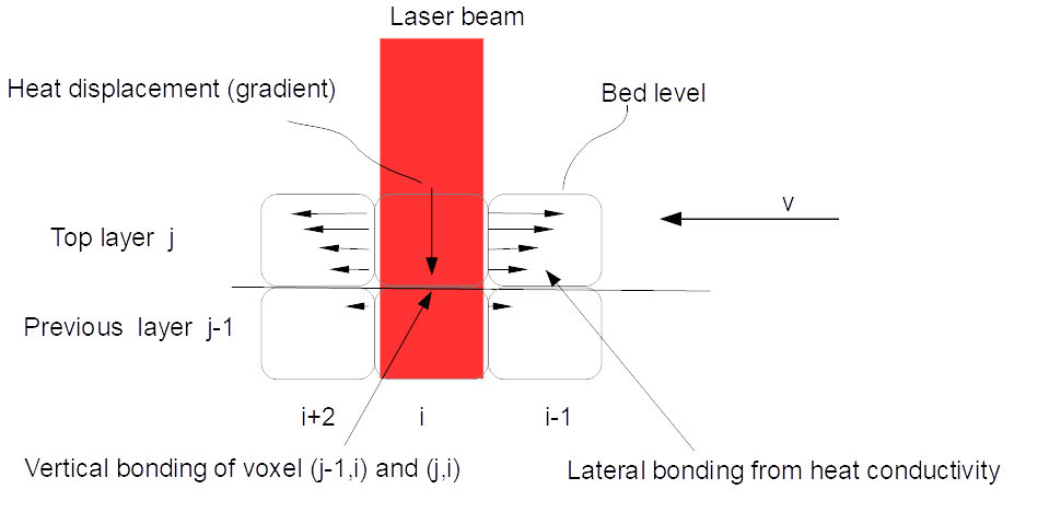
Fig 1. Created with GIMP.

Fig 2.
A Comprehensive Approach to Evaluating SLS Machine Capabilities with BPE and EER
Achieving exceptional print quality in Selective Laser Sintering (SLS) hinges upon precise beam positioning. This article introduces the Effective Energy Ratio (EER) as a crucial companion metric, unveiling a deeper understanding of the impact of beam angle on energy distribution and print quality. Together, BPE and EER empower a comprehensive evaluation of SLS machine capabilities, paving the way for optimized printing.
Beam Positioning Error (BPE):
Definition:
BPE measures the overall deviation of the laser beam from its intended position and angle across the build plate, assessing both spatial and angular inaccuracies.
Measurement:
Beam Location Error (mm): measured deviation of the beam’s center point from its target.
Positioning errors are induced by the beam’s deviation angle from perpendicularity.
Calculation:
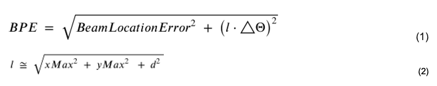
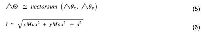
Where Θ is the incident angle and ΔΘ is the error at a specific location in radians, xMax and yMax are the distance from the center of the bed to the tested coordinate.
Units: mm for dimensions and radians for Θ and ΔΘ.
Interpretation:
Lower BPE values indicate better beam positioning and potentially higher print quality. Acceptable thresholds depend on printer technology and application requirements.
Advantages:
Integrates key factors, provides quantitative assessment, facilitates comparisons, guides printer selection and optimization.
Effective Energy Ratio (EER):
Definition:
The Effective Energy Ratio (EER) quantifies the percentage of laser energy delivered to the intended voxel, accounting for energy spilled over to neighboring voxels due to the incident angle.
Importance of Theta (Θ):
The angle at which the laser beam strikes the powder bed plays a key role in energy distribution. As Θ increases:
- Beam spreading: The laser beam “fans out” more, depositing energy over a larger area.
- Energy spillage: More energy spills over to surrounding voxels, reducing the amount delivered to the target voxel.
- Decrease EER: Lower EER values indicate less energy delivery and less efficient targeting.
Therefore, Θ directly impacts the effectiveness of energy delivery, making it a crucial factor in optimizing laser sintering for precision and material quality.
EER Calculation:
EER is composed of two components:
- Total energy delivered to the surface ratio E/E0:
cos^4(Θ)
This term, proportional to the fourth power of the cosine of the incident angle (Θ), accounts for the inherent decrease in energy density as the angle deviates from normal (Θ = 0°).
- Energy loss to neighboring voxels:
1 – Θ * Def / hatch
This term represents the fraction of energy lost due to beam spreading at non-normal angles. It incorporates:
- Θ: As Θ increases, more energy spills over to surrounding voxels.
- Def: Beam diameter; larger diameters contribute to greater spillage.
- hatch: Distance between successive laser scans; closer spacing reduces spillage by concentrating energy within the target voxel.
Therefore, the overall EER is calculated as:
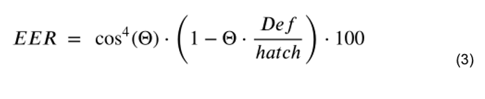
Units: EER is expressed as a percentage (%). While Def and hatch have specific units (e.g., micrometers), their ratio simplifies to a dimensionless factor within the formula.
Interpretation:
Lower EER values indicate less energy spillover and higher efficiency in delivering energy to the desired voxel. This leads to several potential benefits:
- Improved dimensional accuracy: Less energy scattered to neighboring voxels translates to sharper feature definition and reduced shrinkage or swelling.
- Enhanced microstructure integrity: Optimized energy delivery promotes uniform sintering within the target voxel, potentially leading to stronger and more homogeneous material properties.
- Reduced waste and improved sustainability: Minimizing energy spillage promotes efficient material utilization and potentially lowers energy consumption during laser sintering.
Advantages:
EER complements existing metrics like Beam Power Efficiency (BPE) by providing a holistic perspective on energy distribution. It directly focuses on the target voxel, guiding process optimization for enhanced precision, material properties, and overall efficiency.
Visualization:
Imagine a laser beam striking the powder bed at an angle. As the angle increases, the beam “fans out,” depositing some energy in the intended voxel and spilling some to its neighbors. EER quantifies this phenomenon, highlighting the importance of maintaining near-normal angles for efficient energy delivery.
By understanding and optimizing EER, laser sintering processes can achieve improved accuracy, material quality, and overall efficiency, contributing to advancements in additive manufacturing technology.
Benchmarking with BPE and EER:
- Calculate BPE and EER for your machine based on specifications and test prints.
- Establish acceptable thresholds for both metrics considering desired accuracy and application needs.
- Analyze results to identify strengths and weaknesses, compare different machines, and guide optimization strategies.
Advantages of BPE and EER:
Harnessing the combined power of BPE and EER unlocks a profound understanding of your SLS machine.
- Benchmarking without Parts: Leverage machine specifications and simulated beam positioning data to calculate BPE and EER, avoiding the need for physical test prints.
- Setting Thresholds: Determine acceptable BPE and EER thresholds based on desired accuracy, material properties, and application requirements.
- Identifying Strengths and Weaknesses: Analyze BPE and EER results to pinpoint areas for improvement and highlight machine strengths.
- Comparison and Selection: Compare BPE and EER values across different machines to make informed decisions for your printing needs.
- Optimization Strategies: Utilize BPE and EER insights to tailor process parameters, scanner settings, and beam shaping for better print quality.
Conclusion:
Combining BPE and EER provides a comprehensive approach to evaluating SLS machine capabilities. While BPE assesses overall beam positioning accuracy, EER sheds light on energy distribution and the potential for energy spillover, ultimately leading to more informed decisions for achieving high-quality SLS prints.
Benchmark examples calculations
Galvanometer-based SLS printer:

Fig 3.
Fig 3. Shows a galvanometer-based 3d printer. System performance is dictated by optics and printer geometry. The positioning equations are listed below:
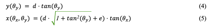
where represents the angular angle following the reflection from the respective Galvo mirror. With a given maximum opening of the respective Galvo we can calculate the bed size:
In this example, we analyze a system where d=1000 mm , e=14 mm , utilized in two print bed sizes calculated from two galvo systems: one with opening angles of ±5° and the second with ±10° degrees opening angles as illustrated in table 1. Def beam diameter is 0.2 mm and hatch distance is 0.2 mm
| Maximum angle (°) | Print bed length (x) [mm] | Print bed width (y) [mm] |
| 5 | 178 | 175 |
| 10 | 363 | 352 |
Table 1.
Eq (4) and (5) show that x is dependent on y location which creates a more complex situation for the controller as y cannot just move independently of x because any change of y location changes the x location. Such a Galvos system is using a closed loop to match the intended location with the target location.
For simplicity let’s consider the combined Galvo errors at 50 microradians. These errors can include offset, linearity, and repeatability (listed in the Galvo datasheet).
The Galvo error is doubling after reflecting from the respective mirror, therefore, each Galvo mirror reflected the this error to 100 microradians for each axis where
calculating the errors for extreme points, by selecting (x_max, y_max) and finding ΔΘ by calculating the vector sum of for , xMax and yMax and d:
Applying for 5° system:
eq (5) (6) yield ΔΘ = 141 micro radians and l = 1008 mm. BPE is now calculated by eq (1) where we assume the beam location error is 0. Resulting in a BPE of 1.42 mm. The result indicates that the beam can be found in the boundaries of a circle of radius 1.42 mm from this specific targeted location.
Applying for 10° system:
The ΔΘ = 141 micro radians and l =1031 mm, resulting in BPE of 1.45 mm.
Calculating EER:
Θ = 7.07° // vector sum
Applying (and converting degrees to radians) the values into eq (3):
And for 10° Galvo, the calculated EER is:
As expected, increasing the angles to 10 degrees per galvo results in a lower EER of approximately 68.94%. This indicates a greater energy spillage (around 31%) compared to the 85.02% efficiency at 5° per galvo.
Lens Free Optical Scanner (LFOS)-based SLS printer:
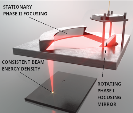
Fig 4.
LFOS disrupts the laser sintering landscape by delivering a uniform, high-fidelity beam across the entire print surface. Unlike traditional galvanometer systems, which project a focused beam on a curved path, LFOS maintains a perfect focus on a flat plane, regardless of the printing area. This translates to several key advantages:
- Unmatched Efficiency: The constant perpendicular incidence, combined with virtually no beam spreading, leads to a theoretical EER of 100%, significantly exceeding the typical 68-85% range of galvanometer systems. This translates to minimal energy spillage, reduced material waste, and potentially lower energy consumption.
- Superior Precision: LFOS accuracy relies solely on its high-precision optical components, independent of the printer’s mechanical movement. This eliminates potential inaccuracies associated with traditional scanners, resulting in exceptional dimensional accuracy and consistent part quality.
- Unleashing Speed and Power: LFOS boasts blazing-fast printing speeds, exceeding galvanometers by up to 65 times. Additionally, it delivers over 25 times the energy than a Gavo system.
In essence, LFOS transcends the limitations of conventional scanning methods, ushering in a new era of efficient, precise, and high-throughput laser sintering. By virtually eliminating energy waste and ensuring consistent printing quality, LFOS has the potential to revolutionize additive manufacturing, paving the way for faster, stronger, and more cost-effective production.
LFOS: Precision Refined, Efficiency Redefined
Beyond its unparalleled energy efficiency, LFOS also excels in delivering exceptional precision, as evidenced by its impressive Beam Placement Error (BPE) figures:
- CASA Model: Achieves a remarkable BPE of 50 micrometers on the Y-axis, significantly surpassing the typical capabilities of galvanometer systems.
- Upcoming Optima Model: Anticipated to push precision even further, targeting a remarkable BPE of just 5 micrometers on the Y-axis.
Unwavering Accuracy: LFOS maintains consistent beam placement across the entire print surface, independent of printer geometry. This consistency translates to exceptionally accurate part production, ensuring dimensional integrity and reproducibility.
Implications:
- Enhanced Part Quality: LFOS’ superior accuracy and precision contribute to the fabrication of parts with finer surface finishes, finer feature details, and tighter tolerances, meeting the stringent requirements of demanding industries.
- Process Optimization: The reduced BPE enables finer control over material deposition and part geometry, potentially leading to optimized process parameters, reduced material waste, and faster print times.
- Expanded Material Possibilities: The ability to precisely control energy delivery and placement could open doors for processing a wider range of materials, including those with demanding sintering requirements.
Conclusion:
LFOS stands poised to transform additive manufacturing through its unprecedented combination of energy efficiency, precision, and speed. By minimizing energy waste, ensuring exceptional accuracy, and accelerating print speeds, LFOS paves the way for a future of manufacturing that is more sustainable, precise, and productive.
| Metric | Galvos (5°) | Galvos (10°) | LFOS (CASA) | LFOS (Optima) | Comment |
| EER (%) | 85 | 69 | 100 | 100 | LFOS maintains perfect EER due to constant normal incidence. |
| BPE (Y-axis, mm) | ±1.420 | ±1.450 | ±0.05 | ±0.005 | LFOS accuracy is independent of noise and angles. |
| Θ Dependence | Yes | Yes | No | No | LFOS performance is consistent across the print area. |
Table 2.
Concluding Remarks: Factors influencing EER and BPE
While the comparison between Galvos and LFOS highlights the clear efficiency and precision advantages of LFOS, it’s essential to acknowledge that several factors can influence the accuracy of EER and BPE calculations and real-world performance:
1. F-Theta Lens Integration:
Installing an F-Theta lens in a Galvo system can mitigate some angular beam spreading issues, thereby increasing EER and improving BPE to an extent. As an example EER equation needs to be adjusted by:
The formula for EER needs to be modified, replacing cos^4(Θ) with cos^2(Θ) to reflect the constant beam speed delivered by an f-theta.
However, F-Theta lenses introduce their own complexities:
- Manufacturing challenges: Large, high-quality F-Theta lenses can be difficult and expensive to produce, limiting their practicality.
2. Telecentric Lenses:
These lenses maintain a constant exit pupil diameter regardless of object distance, potentially improving BPE accuracy. However, the EER equation would still require adjustments to account for the modified beam path and shape and potential energy losses related to the lens itself.
3. Limitations of Formulas:
- It’s important to remember that EER and BPE are theoretical calculations and don’t fully encompass all real-world factors affecting energy delivery and accuracy.
- Material properties, machine calibration, environmental conditions, and other variables can contribute to deviations from idealized values.
Overall, while LFOS technology represents a significant leap forward in laser sintering efficiency and precision, it’s crucial to consider the potential impact of additional factors. Understanding the influence of lens systems, material specifics, and real-world conditions is essential for optimizing laser sintering processes and achieving desired outcomes.
By incorporating these considerations into your analyses and experiments, you can ensure that EER and BPE values accurately reflect your specific operating conditions and guide you towards optimizing your laser sintering processes for exceptional results.
Charles Bibas, CEO of Tecnica, Inc., will be participating at the upcoming Additive Manufacturing Strategies business summit in New York, February 6 to 8, 2024. Barnes will be speaking on the panel “Impact on Operations: Quality.”
Subscribe to Our Email Newsletter
Stay up-to-date on all the latest news from the 3D printing industry and receive information and offers from third party vendors.
You May Also Like
Gorilla Sports GE’s First 3D Printed Titanium Cast
How do you help a gorilla with a broken arm? Sounds like the start of a bad joke a zookeeper might tell, but it’s an actual dilemma recently faced by...
Nylon 3D Printed Parts Made More Functional with Coatings & Colors
Parts 3D printed from polyamide (PA, Nylon) 12 using powder bed fusion (PBF) are a mainstay in the additive manufacturing (AM) industry. While post-finishing processes have improved the porosity of...
$25M to Back Sintavia’s Largest Expansion of Metal 3D Printing Capacity Since 2019
Sintavia, the digital manufacturing company specializing in mission-critical parts for strategic sectors, announced a $25 million investment to increase its production capacity, the largest expansion to its operations since 2019....
Velo3D Initiates Public Offering in a Bid to Strengthen Financial Foundations and Drive Future Growth
Velo3D (NYSE: VLD) has been among a number of publicly traded 3D printing firms that have attempted to weather the current macroeconomic climate. After posting a challenging financial report for 2023,...