
Lens Free Optical Scanner (LFOS): Achieving Higher Standards in SLS/SLM 3D Printing – AMS Spotlight

Abstract
In traditional Additive Manufacturing (AM) using selective laser sintering (SLS) and selective laser melting (SLM), the microstructural characteristics of the finished parts are determined by various process parameters, such as energy density, exposure time, part orientation, and specific part geometry. However, in subtractive material (SM) manufacturing, the microstructure of the material is already set and does not change during the manufacturing process. This makes the AM process more complex, presenting challenges in reducing the number of variables, especially for metal printing where thermal equilibrium must be maintained throughout the process.
The Lens Free Optical Scanner (LFOS), also known as the ØgonTM, patented and manufactured by Tecnica, Inc (New York, USA), was designed to eliminate at least eight major parameters. It stabilizes the microstructural integrity of the resulting print by delivering the same amount of energy to each voxel across the work surface, making it the most viable option for SLS/SLM production. Unlike traditional Galvanometer-based systems, the LFOS uses an open loop system and delivers energy consistently to each voxel across the print area.
In this paper, we will directly compare the galvanometer-based scanner and the LFOS.
Introduction
Below, we will describe the benefits of the LFOS in SLS/SLM Additive Manufacturing by evaluating solutions it offers in response to challenges posed by the traditional Galvanometer-based system (GS). Here are some of the ways in which the LFOS outperforms the GS.
Galvanometer structure
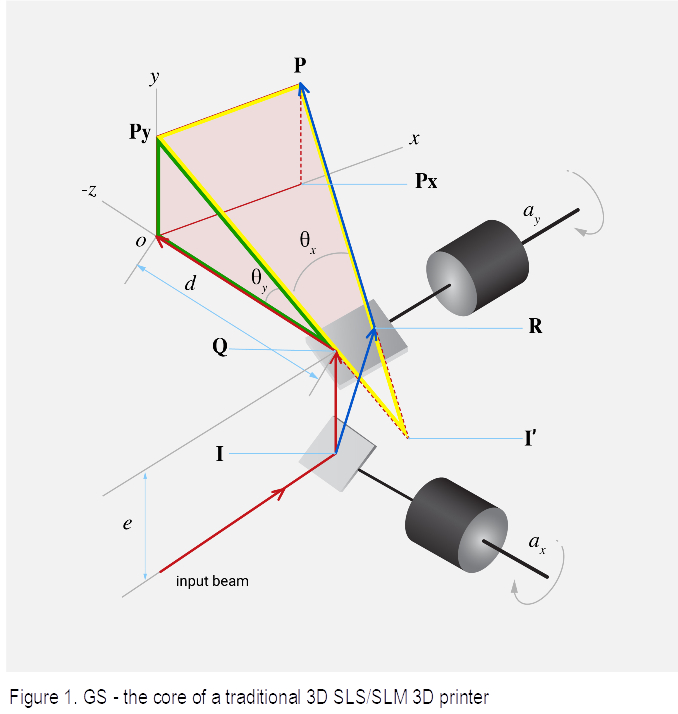
The GS suffers from multiple flaws where the core issues are derived from the focus positioning and the varying of the Optical Path Length (OPL).
As a result, the beam striking the work surface is:
- Changing speed as a function of x,y location
- Changing beam angle with the surface as a function of the x,y location
- Changing beam diameter as a function of the x,y location
- Changing of the beam shape as a function of the x,y location
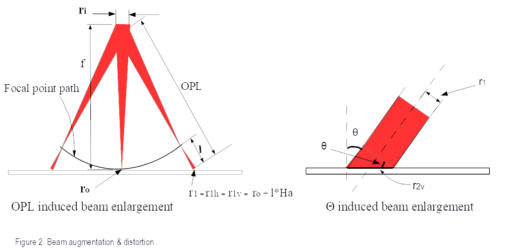
The effects (2) & (3) are illustrated in Figure 2.
Each pixel absorbs different amounts of energy because of the varying beam parameters. An estimate for the energy absorbed by the voxel is expressed by eq (1).
Equation 1.
Where Pl is the laser power, Def the effective diameter (beam normalized diameter at the specific location of the hatch distance), v the beam speed, Lh the layer thickness, and θ is the angle between the normal to the surface and the beam.
Eq (1) shows why parts printed away from the print center are receiving a reduced amount of energy. Eq (1) also demonstrates that printers with a large Field of View do not deliver sufficient energy to the far away from the center voxels.
Beam normal to the surface is desirable:
Consider a printing system where the targeted voxel absorbs the exact amount of energy needed for sintering with its neighbors, as illustrated in Figure 3 where maximum energy is absorbed by the surface (the beam is normal to the print surface). Please note: this is a simplified model to illustrate the beam interaction with the surface and subsurface.
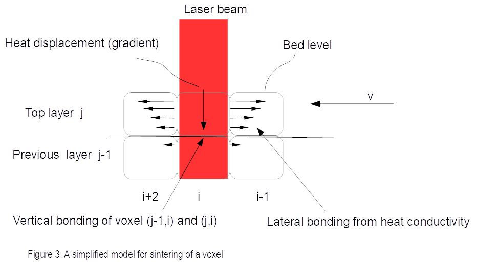
The voxel bonds laterally with the neighboring voxels by heat conductivity as the neighboring voxels are at a small delta temperature below the melting point, and therefore need a small amount of energy/heat to sinter or melt. The bonding of the top voxel(i, j) to the voxel below it (i, j-1) is helped by two heat components: heat conductivity and what is left from the beam energy.
While the beam propagates through the layer it will deliver less energy because: 1. Some of the light has been transformed to energy 2. The beam travels out of its focus point (bed level), therefore the energy density decreases.
The system needs to be in thermal equilibrium during the print process. In this ideal setting, it is more manageable to keep thermal equilibrium compared to a Galvanometer based system where the beam changes its angle with the surface.
Consider now a print system where the beam is not normal to the voxel. In such a case, the beam will be propagating into the layer and deliver lateral heat to the neighboring voxels as illustrated in Figure 4.
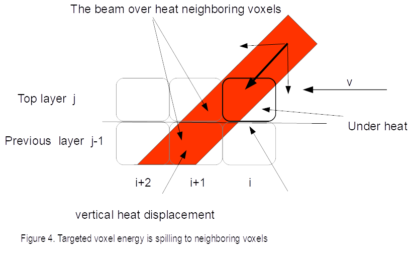
The voxel not only loses energy due to eq(1), but also because the heat gradient (the way heat is distributed) has more lateral components, as the beam spreads into the next voxel diagonally rather than vertically. This results in a significant loss of the vertical bonding energy.
This thermodynamic model is more challenging than our first model, as the angle changes for every voxel, hence increasing the number of the parameters that need to be accounted for to achieve thermal equilibrium.
Beam direction matters:
In Figure 4 the next voxel in line (i+1) is preheated by the present beam aimed for voxel (i), while if the beam will be moving in reverse the next voxel would not receive preheat as in Figure 4. This is important, because the total amount of energy delivered to the voxel is varying if we change direction. Adding another parameter to the thermodynamic model.
Lens Free Optical Scanner:
Tecnica, Inc., developed and patented the Lens Free Optical Scanner for delivering a consistent amount of energy to each voxel. LFOS is composed of two mirrors, the first rotating mirror (M1) and second stationary mirror (M2). Figure 5 shows its working principle.
Because M2 is a circular ring of radius R, it imposes a focus at a distance d = R/2 for a sphere and R for a conical ring on the x dimension of the beam (Fig. 5). The y component of the beam is focused by the M1 y surface component, and the M2 profile with the focus is selected to match the x dimension distance at R/2 from M2.
The LFOS functions performed on the beam source are:
- Beam steering: first, it is steered by M1 from the beam source optical axis, then by M2 back parallel to the beam source optical axis;
- Beam revolution around the beam source: the output beam revolves around the beam source optical axis;
- Beam rotation around its local optical axis;
- Beam focusing: the beam is fully focused in both directions at the work surface.

Figure 5. Working principle of the LFOS
The LFOS delivers a consistent beam of light to the work surface, eliminating the errors that the GS experiences. As a lens-free system, it eliminates any distortion caused by lenses and makes installation easier because the optical axis is determined during production rather than by the printer’s design. Additionally, the mirror in the LFOS can sustain more energy, allowing the CASA II to handle up to 20 times more energy than a GS. Moreover, the LFOS’s constant rotational speed allows it to reach speeds comparable to a polygonal scanner, resulting in a scan speed that is 65 times faster than the fastest GS.
FAQ
Q: Why is f-theta not mentioned, as it is known to fix some of the GS issues.
A: f-theta mostly mitigates the speed, therefore reducing the cos^4 to cos^2 in eq (1). Additionally, it is not ideal, as the beam size and energy density vary. Moreover, f-theta is not scalable beyond a certain size.
Q: Is the LFOS available for OEM, and how do you control it?
A: Yes, we do offer the printhead as an OEM module to purchase. We provide the printhead with the embedded controller and modulator.
Q: GS is used for scanning in the medical field with a great degree of resolution. Why the same resolution cannot apply to AM?
A: In sensing, only accuracy needs to be addressed when the data collected is post processed to render a layer with adjustments performed on the data. In marking, collecting the data could aid to quantify printing errors but not repairing errors by unmarking/erasing.
Comparison
| GS | Øgon | |
| Feature |  | 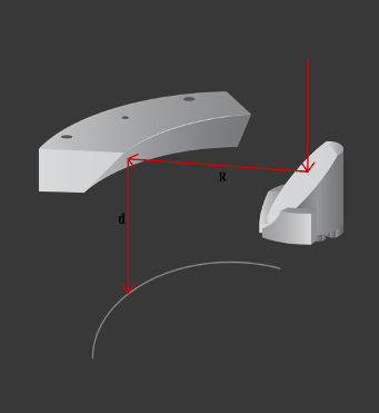 |
| Energy density | ★★✰✰✰
| ★★★★✰
|
| Temperature predictability | ★★✰✰✰ | ★★★★✰ |
| Position | ★★✰✰✰ Nonlinear | ★★★★✰ Linear & Symmetrical |
| Speed | ★✰✰✰✰ Nonlinear | ★★★★✰ Linear |
| OPL | ★✰✰✰✰ | ★★★★★ Always constant |
| Θ | ★✰✰✰✰
| |
| Beam Size & Shape | ★★✰✰✰ | ★★★★★ Always constant |
| Position | ★★✰✰✰ Nonlinear | ★★★★✰ Linear & Symmetrical |
| Speed | ★✰✰✰✰ Nonlinear | ★★★★✰ Linear |
| Modulation | ★★✰✰✰ | ★★★★✰ |
| Stability | ★★★✰✰ | ★★★★✰ |
| Scalability | ★★✰✰✰ | ★★★★✰ |
Table 1: Head-to-head comparison between the GS and the ØgonTM
The head-to-head analysis in this paper has shown that the ØgonTM Lens Free Optical Scanner solves galvanometer scanners’ fundamental problem of inconsistent energy deposition. While the surface beam speed, optical path length, and angle of incidence (which affect the beam size and shape) vary as the galvanometers scan the work surface, these properties remain constant as the ØgonTM operates.
The y-dimension of the ØgonTM print area can be increased by using a longer linear actuator. Although the x-dimension is limited by the size of the M2 mirror, the print head is portable so that it can be mounted on a robot to cover a larger print area in a sequence of stripes. This kind of scanning would have a repeatability error of 50 micrometers for a typical robot with a 2-meter arm. This is an easy adaptation of existing workshops utilizing their robots.
The ØgonTM laser energy output can be modulated by pulse width and/or analog intensity and the scanner consistently delivers 100% of that energy to each pixel across the entire work surface. This precise control of energy deposition and surface temperature makes it the ideal platform for developing new algorithms for additive manufacturing metal printing.
It would be interesting to use the ØgonTM to experimentally validate some of the temperature-prediction models for metal printing. For example, the ØgonTM modulator could incorporate the Mirkoohi model [1] coupled with machine learning to predict the z-axis of the melt pool, which would provide superior temperature prediction.
Conflict of Interest Statement
Charles Bibas reports the following details of affiliation or involvement in an organization or entity with a financial or non-financial interest in the subject matter or materials discussed in this article.
The author is the CEO & Founder of Tecnica, Inc. A corporation that is utilizing the Lens Free Optical Scanner (LFOS) in 3D printing technology. The author is also the inventor of the LFOS holding four (4) US patents and more than a dozen international patents in the field of Optics and Additive manufacturing technology..
More reading and references
For thermodynamic model for additive material
- [1] Mirkoohi E. et al, 2018, ‘Thermal Modeling of Temperature Distribution in Metal Additive Manufacturing Considering Effects of Build Layers, Latent Heat, and Temperature-Sensitivity of Material Properties’
- [2] Song, L., Bagavath-Singh, V., Dutta, B. et al., 2012, Control of melt pool temperature and deposition height during direct metal deposition process. Int J Adv Manuf Technol 58, 247–256 (2012). https://doi.org/10.1007/s00170-011-3395-2
Galvanometer material:
- [3] Xianyu Meng et al, 2019, ‘2-D Scanning Galvanometer Error Analysis and Its Correction’, Phys.: Conf. Ser. 1345 022068
- [4] Zhang W. et al, 2019 Mar 18, ‘An Online Calibration Method for a Galvanometric System Based on Wavelet Kernel ELM. Sensors (Basel)’, 19(6):1353. doi: 10.3390/s19061353. PMID: 30889895; PMCID: PMC6471072.
- [5] Huang Jigang, Qin Qin, Wang Jie, and Fang Hui, “Two Dimensional Laser Galvanometer Scanning Technology for Additive Manufacturing”, International Journal of Materials, Mechanics and Manufacturing, Vol. 6, No. 5, October 2018
Polygonal scanners:
- [6] Duma,V. F., 2019, ‘Laser scanners with oscillatory elements: Design and optimization of 1D and 2D scanning functions. ‘, App. Math. Model. 67 (2019) 456-476.
Author’s references:
- [7] Bibas, C. Lens-Free Optical Scanners for Metal Additive Manufacturing. JOM 74, 1176–1187 (2022). https://doi.org/10.1007/s11837-021-05044-8
- [8] Bibas C., 2021, “Øgon, A REVOLUTIONARY NEW LENS FREE OPTICAL SCANNER (LFOS) FOR ADDITIVE MANUFACTURING (AM)”, University Of Texas, SFF conference 2021. – Chosen best papers list.
- [9] Bibas C., Proceedings Volume 12170, Advances in 3OM: Opto-Mechatronics, Opto-Mechanics, and Optical Metrology; 1217006 (2022) https://doi.org/10.1117/12.2600487. Event: Advances in 3OM: Opto-Mechatronics, Opto-Mechanics, and Optical Metrology, 2021, Timisoara, Romania
- [10] Bibas C., 2019, ‘Beam director with improved optics’, US Patent 10,416,444
- [11] Bibas C. et al., 2016, ‘Beam director’, US Patent 9,435,998
Subscribe to Our Email Newsletter
Stay up-to-date on all the latest news from the 3D printing industry and receive information and offers from third party vendors.
You May Also Like
Gorilla Sports GE’s First 3D Printed Titanium Cast
How do you help a gorilla with a broken arm? Sounds like the start of a bad joke a zookeeper might tell, but it’s an actual dilemma recently faced by...
Nylon 3D Printed Parts Made More Functional with Coatings & Colors
Parts 3D printed from polyamide (PA, Nylon) 12 using powder bed fusion (PBF) are a mainstay in the additive manufacturing (AM) industry. While post-finishing processes have improved the porosity of...
$25M to Back Sintavia’s Largest Expansion of Metal 3D Printing Capacity Since 2019
Sintavia, the digital manufacturing company specializing in mission-critical parts for strategic sectors, announced a $25 million investment to increase its production capacity, the largest expansion to its operations since 2019....
Velo3D Initiates Public Offering in a Bid to Strengthen Financial Foundations and Drive Future Growth
Velo3D (NYSE: VLD) has been among a number of publicly traded 3D printing firms that have attempted to weather the current macroeconomic climate. After posting a challenging financial report for 2023,...