The Building Blocks of Directed Energy Deposition Design


My kids love creating structures with Legos, Duplos, and boxes. Some days they build big houses with simple walls and others detailed spaceships with intricate features. Their block choice dictates the structure they build, or they pick the blocks based on the resolution they desire. Directed Energy Deposition (DED), a family of Additive Manufacturing (AM) processes, is quite similar in that a designer has a set of geometric “building blocks” she can combine to make a structure. The feature resolution is based on the size of the melt puddle and part volume on the size of the motion platform, but I am getting ahead of myself.
First, let us break down this AM process, as we do in TBGA Training, by asking (3) questions:
How is a Layer formed?
The layer is created with the energy coming together at a focused point to create a melt puddle which is propagated to form a bead.
Common motion platforms include robots and gantries; additional degrees of freedom are often added with turn or flip/tilt motion for the part fixture and substrate.
How is Energy applied?
Thermal or kinetic energy is used to convert particles or filament (wire) into a solid layer.
Today we are contemplating Fusion (thermal) DED, where the material is melted. Any compatible heat source and material combination can be used including laser, electron beam, plasma, and arc. Other processes use friction, ultrasonic, or kinetic energy.
How is the Material applied?
Wire via a feeder or powder particles fed with a carrier gas.
Some process and material combinations require specialty incoming material chemistries, but many can use standard “off the shelf” weld wire and coarser cuts of powder, which can be less expensive.
In a nutshell, DED is all about propagating a molten pool of metal to form a series of beads that solidify to form geometries. The bead needs a surface to attach to, so the process begins with a substrate, or base, to start deposition. Deposition is often followed by a heat treatment, partial or full machining (or other surface smoothing step), and non-destructive evaluation. DED is also often combined with other welding or cladding processes to create a final part. Two common process set ups are shown in Figure 1. The part shown in the figure is a partially machined titanium demonstrator manufactured by GKN Aerospace using Laser Wire DED showing geometry “building blocks” of straight walls, curved walls, and multiple intersections. Another characteristic of DED processes is a wide range of possible part sizes ranging from a few cubic centimeters to many cubic meters.
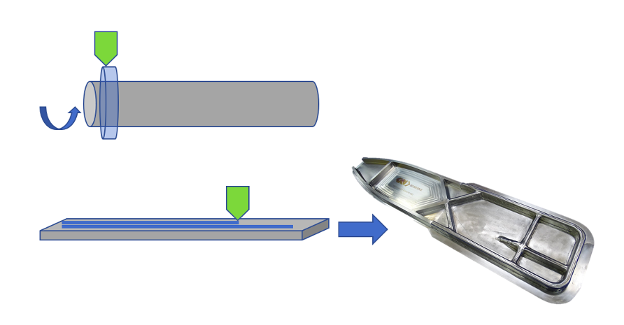
Figure 1: Two deposition setups showing (top) cylindrical substrate with a secondary turning axis and (bottom) flat plate substrate. Gray denotes substrate, green deposition head, and blue deposited material. Part image source: GKN Aerospace.
Designing for DED
Designing for DED can be broken down into the opportunistic aspects, called Design for AM (DfAM), and the restrictive aspects, called Modify for AM (MfAM), as described in a previous TBGA article. Tables 1-3 illustrate key design considerations before, during and after deposition and note whether they are DfAM or MfAM considerations. The supporting software is just as important as calibrated hardware in a successful DED build. Part slicing, deposition path planning, which is the sequence of deposited beads, and control of layer (bead) height are critical, and all have cross-cutting and inter-related impacts on design.
Table 1: Key DED Design Considerations for Substrate and Feedstock
| Substrate | Feedstock | |||
| Consideration | Size, material, and temper
|
Use of substrate as sacrificial or integral to part | Deposition of different materials and functionally graded materials | Material form effect on surface finish |
| Impact | Insufficient heat dissipation, inability to fit final part in DED preform | Design flexibility, part performance, and cost | Ability to design with location specific material performance | Some processes may require finish machining or other surface smoothing |
| DfAM or MfAM | MfAM | DfAM | DfAM | MfAM |
Table 2: Key DED Design Considerations for Deposition
| Deposition | ||||
| Consideration | Melt pool size and bead width/height | Motion platform degrees of freedom | Start / Stop / Transition locations with different material properties | Thermal cycling and stress build up create part warpage |
| Impact | Dictates deposition geometries, feature resolution, and number of beads required | Features may be limited by self-supporting angle | Add sacrificial deposition for Start/Stop outside of final part or locate in less critical area | Part may require intermediate stress relief during deposition or other design compensation |
| DfAM or MfAM | DfAM and MfAM | DfAM and MfAM | MfAM | MfAM |
Table 3: Key DED Design Considerations Post-Deposition
| Machining | Non-Destructive Evaluation | |||
| Consideration | Fixturing and datum locations | Ability to alternate deposition and machining | Surface interface with NDE and/or geometry compatibility | Thinner sections in very large parts |
| Impact | Inability to machine final part from preform | Unitization, design flexibility, and cost | Requires more expensive NDE, intermediate machining prior to NDE or inability to use that feature | Ability to perform NDE to a greater level of sensitivity |
| DfAM or MfAM | MfAM | DfAM | MfAM | DfAM |
DED Applied
I recently checked in with several leading developers of DED processes to showcase the variety of designs being built. The first is my former GKN Aerospace team, who are developing titanium Laser Wire DED with Oak Ridge National Laboratory in Tennessee. They have explored process parameters to create different bead widths to build walls ranging from 3mm up to 20mm, as shown in Figure 2. Their system has a flip/tilt fixture for the substrate which adds 2 additional degrees of freedom to the robot mounted deposition head enabling the exploration of more complex overhangs and double-sided deposition, which is great for managing distortion; Figure 3 shows a part built with double sided deposition that will be subsequently machined 100%. The Oak Ridge National Laboratory team used the same process to produce the fin shaped part shown in Figure 4; the diamond shaped holes showcase a design feature tailored to process capability.
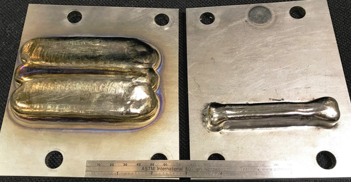
Figure 2: Two 3 bead wide walls built on the same Laser Wire DED system using different key process variables. Source: GKN Aerospace.
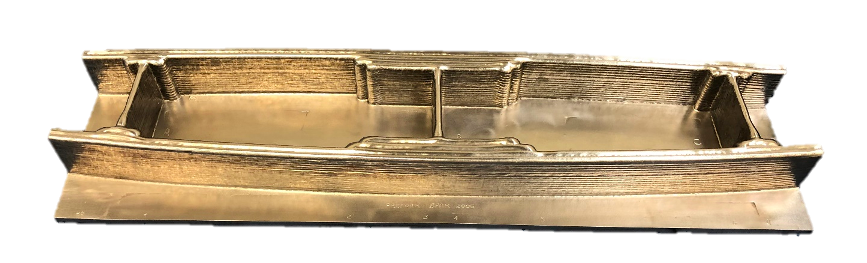
Figure 3: Titanium Laser Wire DED deposited part. Source: GKN Aerospace.

Figure 4: Partially machined fin shaped titanium Laser Wire DED deposited part showing design examples of process compatible holes. Source: Oak Ridge National Laboratory Manufacturing Demonstration Facility.
Moving out to Colorado, the aluminum article shown in Figure 5, was produced as a single component without parasitic support material using Big Metal Additive’s multi-axis hybrid DED and machining process. This seating module for a marine transport vehicle is 6 feet wide, 2 feet deep and almost 3 feet tall. The design originates from an inspiration of generative design, and the CAD model was created from convergent modeling methods. There are overhang angles greater than 45 degrees and several converging and diverging connecting geometries with this challenging structure.
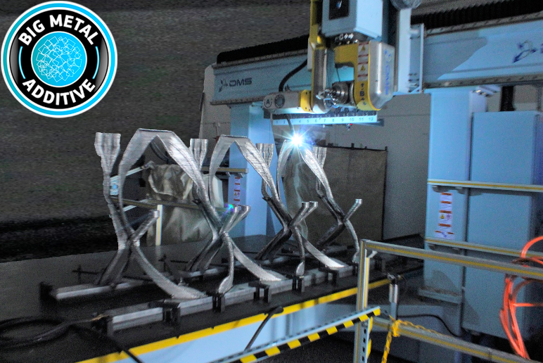
Figure 5: Aluminum DED structure built by Big Metal Additive.
DED enables the use of multiple materials for tailored performance. For components, like the rocket nozzle shown in Figure 6, regions with concentrated heat loads can be fabricated out of higher temperature materials while other areas can be fabricated out of higher strength materials. Built by FormAlloy in California with a small melt puddle powder-fed DED process, the rocket nozzle with internal cooling channels was built first, followed by the addition of the flange and the clad on the outer diameter. This component demonstrates the ability to build, add features and/or repair, and clad with a single DED process.
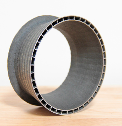
Figure 6: Rocket nozzle built with powder-fed DED by FormAlloy.
These examples show just a few of the design possibilities enabled by DED but many more geometries are being created including:
- 1+ meter satellite fuel tank domes built with Electron Beam / Wire DED by Lockheed Martin
- Tooling repair / re-manufacture for automotive dies using hybrid powder-fed Laser DED and machining
- Like for like replacement flying 787 floor grid brackets built by Norsk Titanium
- Large steel bridge built by MX3D in Amsterdam (I stood on an early prototype!)
DED as a Tool
DED is a tool that is finding its way into quite a few manufacturing toolboxes, though I doubt Wallace D. Wattles was considering DED when he said, “It is essential to have good tools, but it is also essential that the tools should be used in the right way.” Whether contemplating our next family build activity or the build plan for a large metal component, it is critical to select the right process for the job. Understanding the DfAM and MfAM characteristics of specific processes is a fantastic starting point for a DED design journey.
Subscribe to Our Email Newsletter
Stay up-to-date on all the latest news from the 3D printing industry and receive information and offers from third party vendors.
Print Services
Upload your 3D Models and get them printed quickly and efficiently.


You May Also Like
3D Printing News Briefs, July 9, 2026: RIMPAC 2026, Software, Housing, & More
In today’s 3D Printing News Briefs, Massivit continues its focus on aerospace and defense manufacturing, and Meltio is collaborating with Phillips Corporation for RIMPAC 2026. Moving on to software, AMIS...
3DPOD 304: Precast Concrete AM with Greg Kerkstra, Mangrove
Greg Kerkstra is part of a family business that leads in the precast concrete industry. They’ve now turned to Progress Group’s large-format binder-jet concrete technology, which we covered here in...
3D Printing News Briefs, June 10, 2026: Grand Opening, Photoresins, Footwear, & More
We’re starting with some exciting news in today’s 3D Printing News Briefs: Stratasys just celebrated the opening of its new North American headquarters in Minnesota. Moving on, Nanoscribe is scaling...
Wells Fargo Backs ICON in Landmark Milestone for 3D Printed Housing
Qualification is an indispensable step on the path to legitimization for any new technology, but it’s still just one step: markets tend to remain unswayed without a co-sign from an...