Ensuring Metal Additive Manufacturing Part Quality with Pre-Build Calibration


Real-time monitoring systems and post-print data analysis are much talked about subjects when discussing quality assurance in metal additive manufacturing (AM aka 3D printing) these days. But an often-overlooked aspect of consistently making high-quality parts happens long before the print: pre-build calibration.
As it pertains to manufacturing, calibration ensures that a parameter being measured correlates to some agreed-upon value that falls within the limits of what would make a good manufacturing process. Calibration is an essential component of qualifying parts and processes for acceptance in almost all critical industries served by metal AM.
Industry-specific standards are still relatively immature for metal AM, and many standards organizations (ASTM, SAE, AWS, API, etc.) are working on developing or refining their documents. NASA was one of the first organizations to publish such guidelines in October 2017 with their Standard for Additively Manufactured Spaceflight Hardware by LPBF (MFSC-STD-3716) and the accompanying Specification for Control and Qualification of LPBF (MFSC-SPEC-3717), which have both served as a foundation for several of the other organizations and standards bodies. Many of the NASA requirements for confidence in printed part quality – including calibration – have flowed down to the newer standards.
According to MFSC-SPEC-3717, “Calibration is effective only when maintained continuously. For pragmatic reasons, confirming calibration is not feasible on a pre-build basis. This time-based calibration interval is set as a compromise between production efficiency and process assurance.” This very important statement essentially says that the lack of ability to calibrate a metal AM machine before each build forces manufacturers to choose between production efficiency and quality assurance.
However, while it may have been true when the standard was published in 2017, it is no longer the case, as pre-build calibration is not only feasible, it is a reality. Available now on next-generation metal-AM systems, this new capability is ready to help vendors maximize production efficiency and process assurance simultaneously rather than forcing them to sacrifice one for the other.
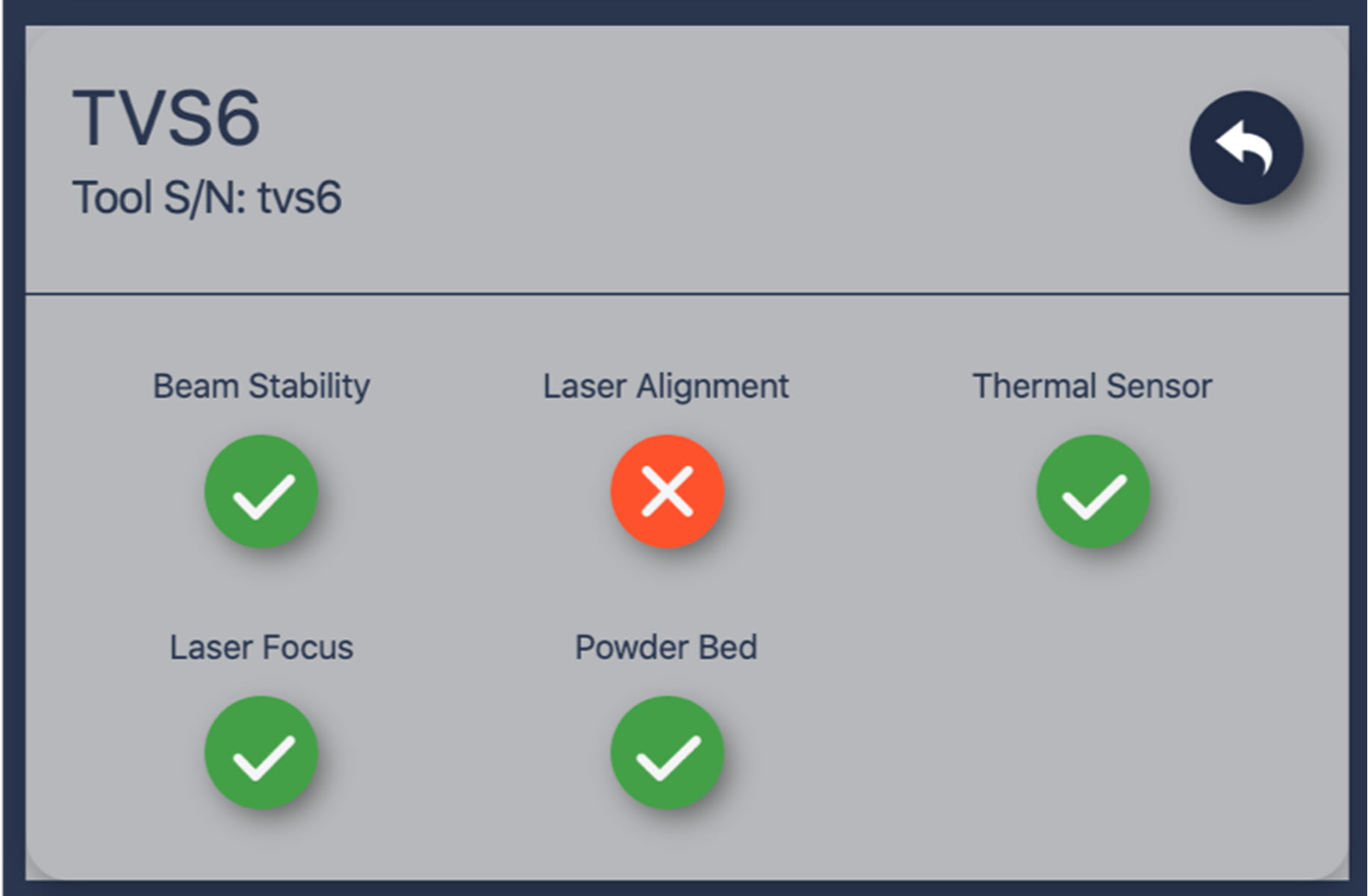
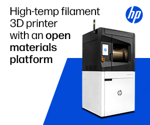
Image 2. Machine health in today’s advanced AM systems can be checked via a single click to ensure powder bed quality, sensors, and optics are calibrated and in optimal condition, and will not compromise part quality.
Calibrating optics
The optics in a metal AM system include one or more lasers and related equipment. They are critical to performing the L-PBF welding process, in which very thin layers of metal powder are melted, one of top of another, to produce a component part. Measured in microns, each layer is generally thinner than the diameter of a human hair, and there can be tens of thousands of layers in any given component. This is why calibration is so key. If a laser in an L-PBF system is not pointed in the right place with the right power and moving at the right speed, then the quality of the component being manufactured will likely be compromised. The problem is compounded on multi-laser systems, where the calibration must also be consistent between individual lasers.

Image 3. Without pre-build calibration laser-alignment, drift can occur over subsequent layers in an AM build.
MFSC-SPEC-3717 specifies several metrics, including laser focus and alignment, that must be calibrated at least every 90 days in order for the additive manufacturing process to remain qualified and the components parts produced be labeled as conforming. NASA does not specify how these metrics are to be calibrated, but does concede that “lasing purposeful markings into a flat, solid plate and evaluating the markings against metrics (based upon past performance) may provide sufficient evidence of scanner head health.”
This method of calibration, albeit a standard practice in the industry, is not only time-consuming, but it also carries a substantial risk of inconsistency. It is an almost entirely manual process, which means that there are many inherent sources of variability. Yet it continues to be used because incumbent AM equipment vendors in the past have simply not had access to better methods.
To calibrate laser focus, for example, many machine manufacturers call for placing an anodized aluminum plate into the build chamber and carefully setting it to the same height on the build plane as where the material would be printed (remember, microns matter!). Lines are burned into the plate and then taken out and measured to determine which of the tracks is the smallest in diameter, thereby indicating the focus of the laser. In the case of laser alignment, manufacturers again traditionally burn a series of lines onto an aluminum plate or thermal paper. The results are sent, sometimes physically, to a third party that uses an optical Coordinate Measuring Machine (CMM) to analyze the results, generate a calibration file, and send updates back to the vendor for installation by a field-service engineer. More than one iteration is sometimes required, which adds significantly to the total calibration time. Often this process can take a day or more to complete, and such non-productive time can be a significant drag on the cost-of-ownership for such an expensive piece of equipment.
Next-generation AM systems, however, now offer pre-build calibration capabilities that streamline and automate the calibration of machine optics so that the machines do not have to be taken off-line to be calibrated. These new systems measure a variety of metrics—including such things as beam stability, laser alignment, and focus—just prior to running the 3D-printing process. Rather than burning lines on aluminum plates, additive manufacturing end users can run their optical calibrations with the push of a single button without the need for any external measuring equipment, such as power meters or beam profilers. Equally important, this automated process captures a wealth of data that is not available using manual methods of calibration. This data is used to update the system’s calibration tables in real time and make sure that a given component is being manufactured to specification. It can also be compiled over time for use in statistical process control programs and other quality management systems.
Powder-bed calibration
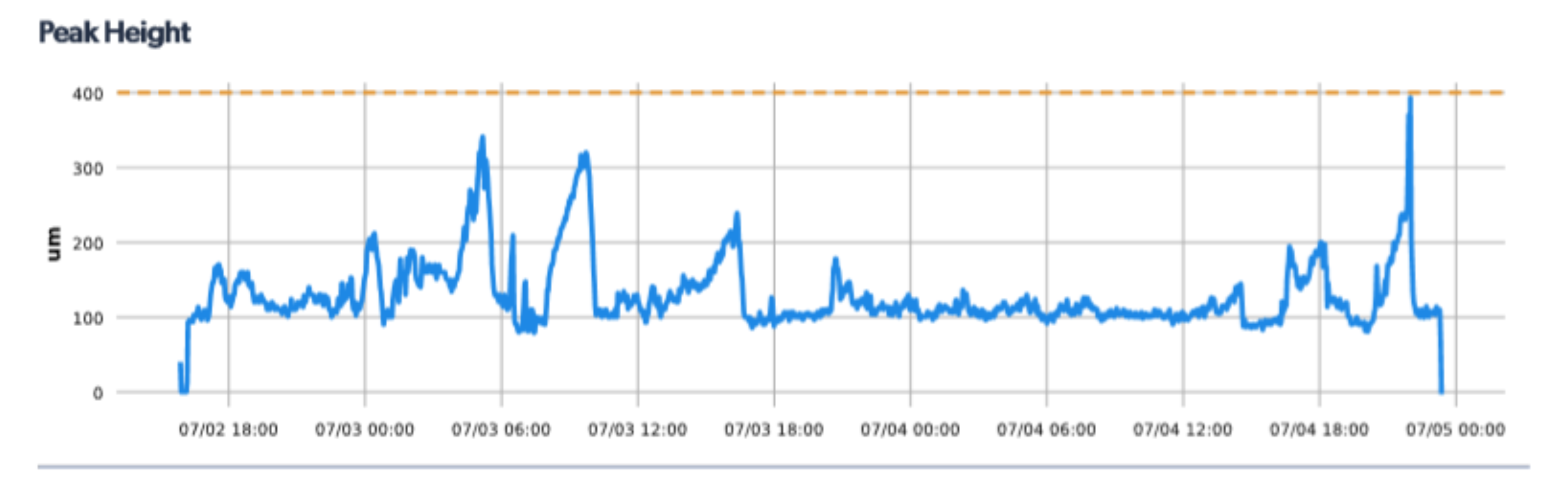
Image 4. Detecting variations in layer height. Quality assurance capabilities in next-gen AM systems track whether a build is showing any signs of unwanted protrusions; crossing the warning threshold will alert the user.
In addition to the optics involved in the L-PBF process, calibrating the quality of the powder bed is key to part quality. Both thickness and uniformity of the powder bed have to be precise to ensure that the lasers melt each layer properly. If the powder bed is too thick, the layer may not melt completely, resulting in lack-of-fusion porosity. If it is too thin, the metal may become overheated and can even be vaporized in the melt pool. Either result can have a very negative effect on the mechanical properties of the resulting part. Proper calibration is essential to delivering accurate layers of powder which, provided the optics are also calibrated properly, yield properly welded layers of metal.
Interestingly enough, and unlike its 90-day optics-assurance guidelines, NASA only requires powder bed quality to be calibrated every 180 days. But six months is simply too long to wait to recalibrate the powder bed, as a number of things can go wrong with the recoating process on any given layer. Much like a windshield wiper on a car leaves streaks when it becomes worn, the recoater may become nicked or damaged in some way, causing it to leave streaks in the powder bed. Although it is such a critical metric, incumbent systems do not typically have a quantitative way to measure the quality and status of the powder bed. Instead, they may take pictures of the powder bed and then do a qualitative analysis of it, but this does not give a vendor actual data on the status of the powder bed itself at a given time.
Next-generation metal AM systems, on the other hand, can check to make sure the recoater is doing its job before and during each and every build. This capability hinges on height-mapper metrology systems, which essentially measure the powder bed topology to a resolution of 15 microns in the z-axis and 100 microns in the x- and y- axes. This truly quantitative measurement ensures that the layer being delivered by the recoater is within specifications in terms of both thickness and uniformity across the build plane.
Ensuring part quality for mission-critical manufacturing
The most obvious benefit of calibrating optics, powder bed quality, and other parameters before a build is identifying problems in a metal AM system before they affect product quality. By nature, component parts created using additive manufacturing processes are not inexpensive. In fact, they can be quite costly and take considerable amounts of time to manufacture. Quality escapes become more expensive the farther down the workflow they are discovered, so it is very important to catch them early, preferably before printing. Additionally, if calibration only occurs every 90 or even 180 days, then a problem may not be detected until after a shipment of parts has been manufactured. If a laser is out of focus or alignment, the power of the laser is not correct for a given job, or the powder is being laid down too thick or unevenly, an entire batch of component parts could be headed toward the scrap heap at a cost of hundreds of thousands of dollars. This is unacceptable and simply unnecessary with today’s next-generation AM systems.
A second, less obvious benefit is that calibrating the critical parameters of an AM system before each build creates a great deal of data that can be used to develop statistical process control around a variety of metrics. By collecting data before each build on optical system status and powder bed quality and other parameters, it is possible to see how the system is performing over time and, by seeing something that is trending out of specification before it actually reaches a control limit, to predict when the machine might need preventative maintenance.
The bottom line is that more frequent and detailed calibrations results in higher-quality 3D-printed products overall, and that the new generation of metal additive machines make this process fast and user-friendly. Improved calibration addresses a key concern that NASA has had with using L-PBF technology for the aerospace industry as, in MFSC-STD-3716, the agency writes that, “The largest latent risk in the utilization of laser powder bed fusion parts in critical spaceflight applications lies in the limitations to verify individual part integrity.” Clearly, the ability for next-generation AM systems to perform a calibration before every single build is now enabling the industry to tackle these concerns, paving the way to acceptance of metal additive manufacturing as the standard for a variety of mission-critical applications.
About the Author
Dr. Zach Murphree is VP of Technical Partnerships at Velo3D. His background includes engineering roles for energy companies, where he was in charge of introducing metal additive manufacturing technology to a Fortune 500 energy company. He earned Bachelor of Science and PhD degrees in Aerospace Engineering from the University of Texas and has been granted more than 35 patents. For more information on support-free 3D metal printing visit https://www.velo3d.com/.
Subscribe to Our Email Newsletter
Stay up-to-date on all the latest news from the 3D printing industry and receive information and offers from third party vendors.
Print Services
Upload your 3D Models and get them printed quickly and efficiently.


You May Also Like
AM Asia Watch: Chinese Company Claims Advances in Titanium Powder Beyond 700C
They’re a familiar sight at trade shows: Chinese powder companies with barren stands lacking parts. There’s maybe some glass vessel with powder in it and a semi-complete data sheet, but...
Aires Tide Designed with AI, Supercomputers, and 3D Printing
The Department of Energy‘s National Nuclear Security Administration (DOE/NNSA) is part of the US government that manages the US nuclear stockpile, helping to upgrade, improve, and maintain nuclear weapons, and...
Largest Publicly Announced, Single Order in EOS History: Beehive Industries Spends $50M on M4 ONYX 3D Printers
Earlier this year, Beehive Industries received a $29.7 million contract to produce its Frenzy 6 and Frenzy 8 engines for the US Air Force. The metal additive manufacturing (AM) user...
Blue Origin’s New Glenn Explosion Comes During Major Manufacturing Push
Blue Origin‘s orbital New Glenn rocket exploded during a hot-fire test at Launch Complex 36 in Cape Canaveral on May 29, setting back the company’s launch ambitions at a time...