Scale Modeling Tutorials: 3D Modeling Basics for 3D Printing, Part Two


In my last article, I began to show you how to use Fusion 360 to create some basic shapes. Here, we take those skills further, exploring more functions in the software before getting into an easy, yet somewhat complex example.
More Basic Functions
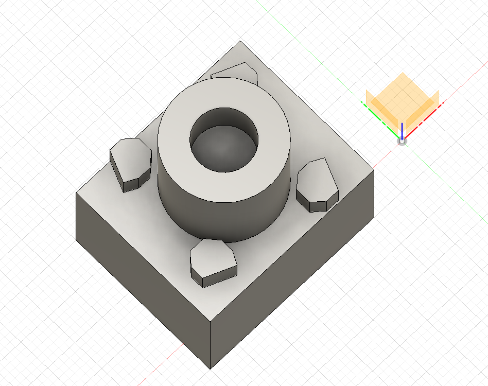
There are a ton of different operations you can perform on objects. Let’s go over one more useful tool. Let’s create an object and duplicate it around the cylinder. Type “L” and click the top surface of our box to create a new sketch and draw a line. You can now draw your own shape using lines. Click somewhere on the box to create the starting point of a line. Move your mouse to draw out the line and click to place the end point. Continue clicking to create more points and lines until you’ve created a shape you like. Make sure you connect your final point to the first point we drew. (In order to extrude a sketch, it’s important that the shape be totally enclosed). Now type “E” and click your newly created sketch to extrude it up. This time, however, select “New Body” in the Extrude window to create a new body and click ok.
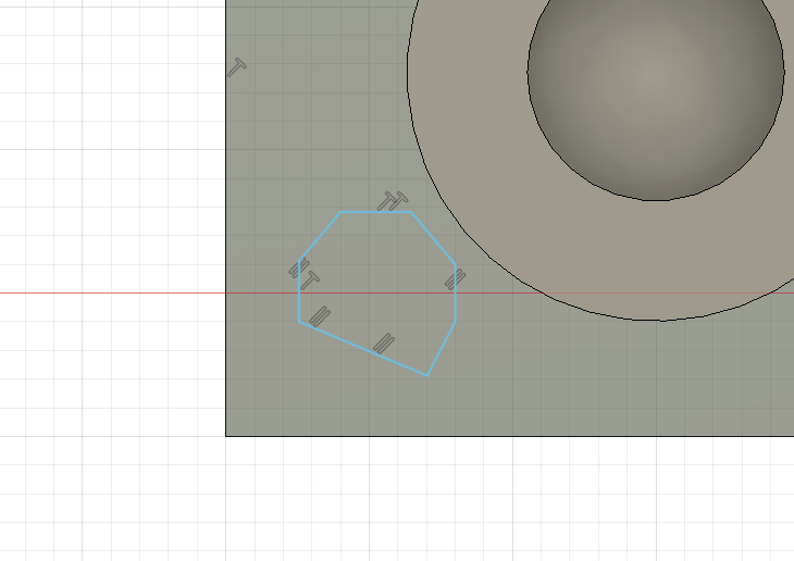
You can select an object simply by clicking on it. Click the new shape we just created and notice that it’s now highlighted in blue. (Note: if your cursor is only able to select faces, click the “Select” dropdown in the top right, click “Selection Priority” and click “Select Body Priority”). You can move the object by typing “M” and dragging it along the arrows, or using the curve symbols to rotate it. You can also duplicate an object by selecting it, clicking it, then typing Ctrl+C, Ctrl+V and moving the new object in the same way.
For now though, let’s create a few shapes around the edge of the cylinder. So type Ctrl+Z to undo any moving or copying and pasting you just did. Now, from the “Create” dropdown in the top left, select “Pattern” and click “Circular Pattern”. You’ll notice a new “Circular Pattern” window. If not already selected, choose “Bodies” from the “Pattern Type” dropdown. Click our newly created shape to select it. It should now be highlighted in the “Objects” field of the window. Right below that, click “Select” in the “Axis” field. Now, hover over the base of the cylinder until it’s highlighted and click the circle. There are a few other objects in the Circular Pattern window, but, for now, let’s just increase the “Quantity” to four and click ok.

It may not be pretty, but you’ve just learned the basics of CAD design and created your first 3D objects. There are plenty of other functions to explore, but the basic process of creating sketches and objects, then manipulating them, can be used to create some pretty detailed models. Let’s quickly create a slightly more interesting model, using those same basic steps.
A Fun Example
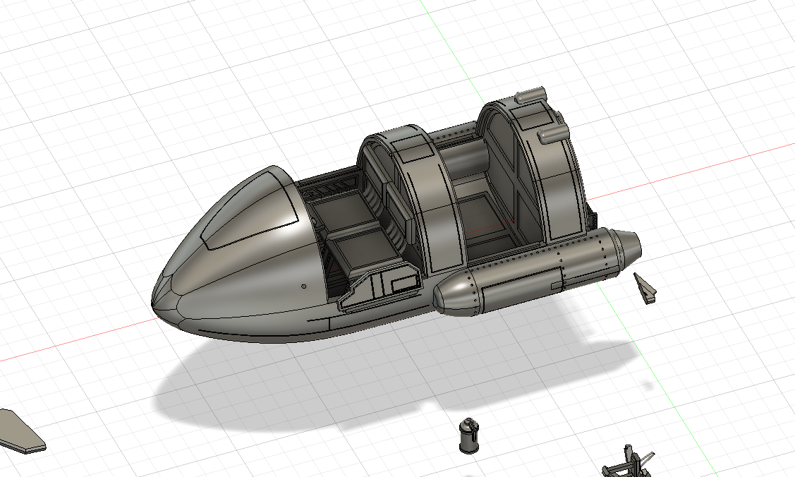
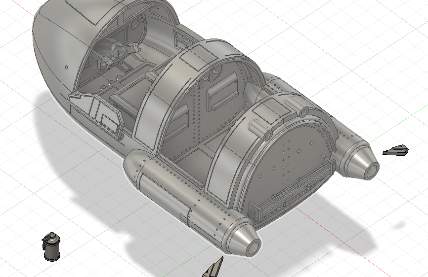
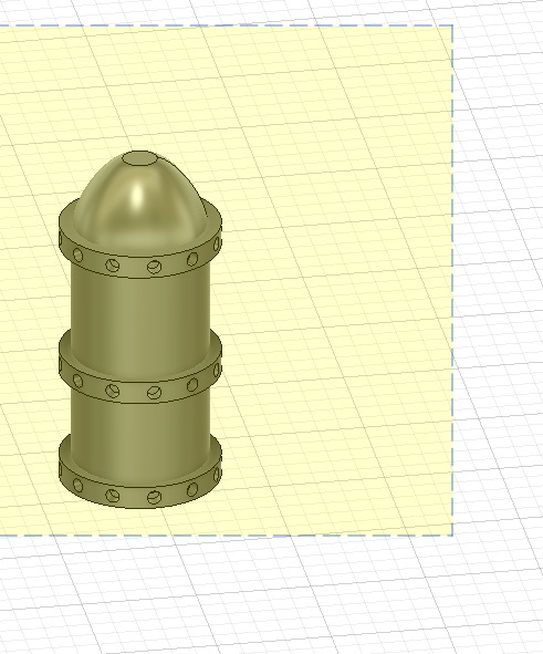
Here is a model of some kind of sci-fi speeder I’ve been working on. I’d like to create a few, small accessories to add to the model once I print it off. I’m going to make some kind of fuel tank or canister to attach to the back of the model. Here’s a quick walkthrough that showcases a few other useful functions.
- Navigate to the back of the model
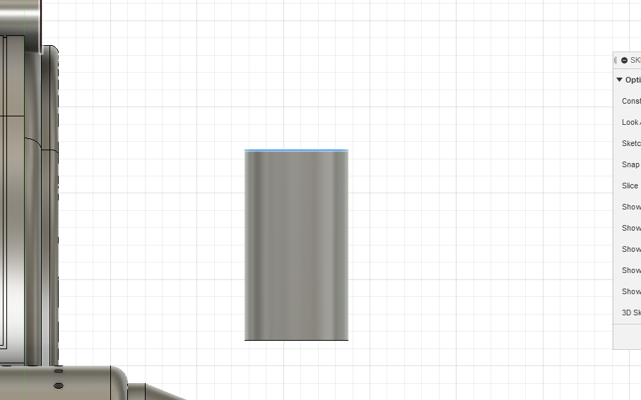
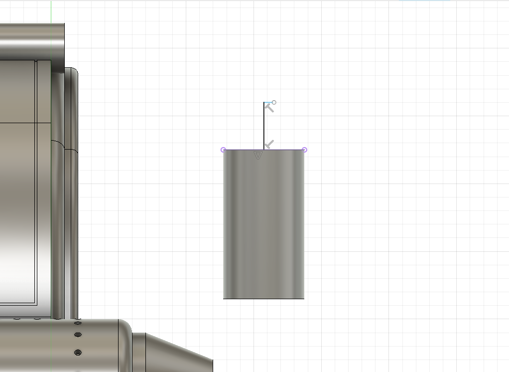
- Type “C” on the XZ plane to create a circle, with the center point somewhere on the X axis

- Type “E” to extrude the circle

- Type “P” to create a new sketch on the XZ axis and click the top of the cylinder to project geometry from the object onto the current sketch. Type “Enter/Return”. (Projected geometry shows up in purple and can be used the same as any other geometry)
- Type “L” to create a line
- Hover over the middle of the top of the cylinder until the triangle appears, indicating the midpoint

- Click and create a line
- Create a second, horizontal line
- From “Create”, select “Create Point Spline” and draw a spline.
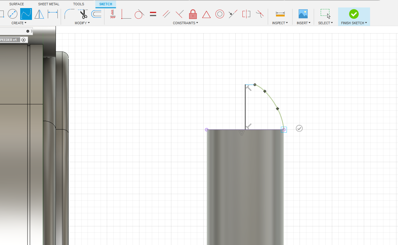
- Finish sketch
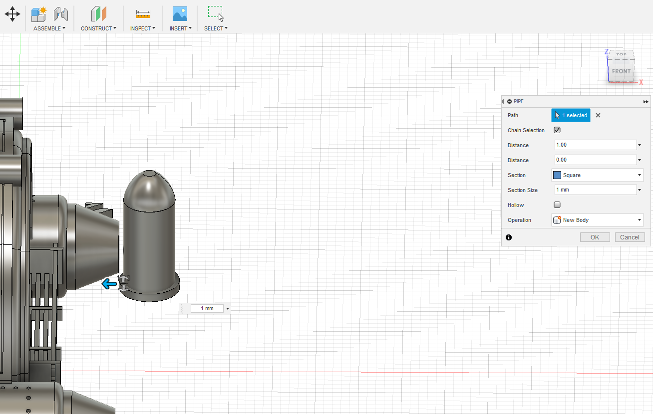
- From the “Create” dropdown select “Revolve”
- Revolve the spline shape around the previously created line

- From the “Create” dropdown select “Pipe” and create a rectangular pipe along the bottom of the cylinder as a new object
- Type Ctrl+C and Ctrl+V to copy and paste the newly created pipe and move it up to the top of the cylinder. Click Enter
- Click “Construct” to create an offset plane (this creates a new plane that can be used to create sketches)
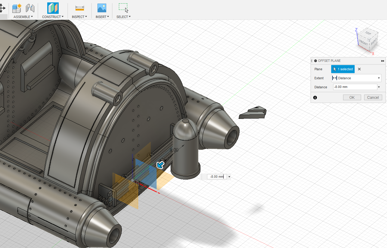
- Select the XZ plane and move the construction plane somewhere past the model
- Click “C” to draw a circle on the new plane
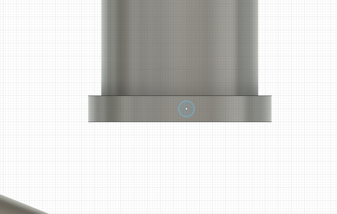
- Draw a .6 mm circle somewhere on the newly created pipe
- Type “E” to extrude the circle
- From the “Extent” dropdown, select “To Object” and select the pipe at the bottom of the cylinder. This will project the circle to the surface of that object
- Select “New Body” and click “OK”
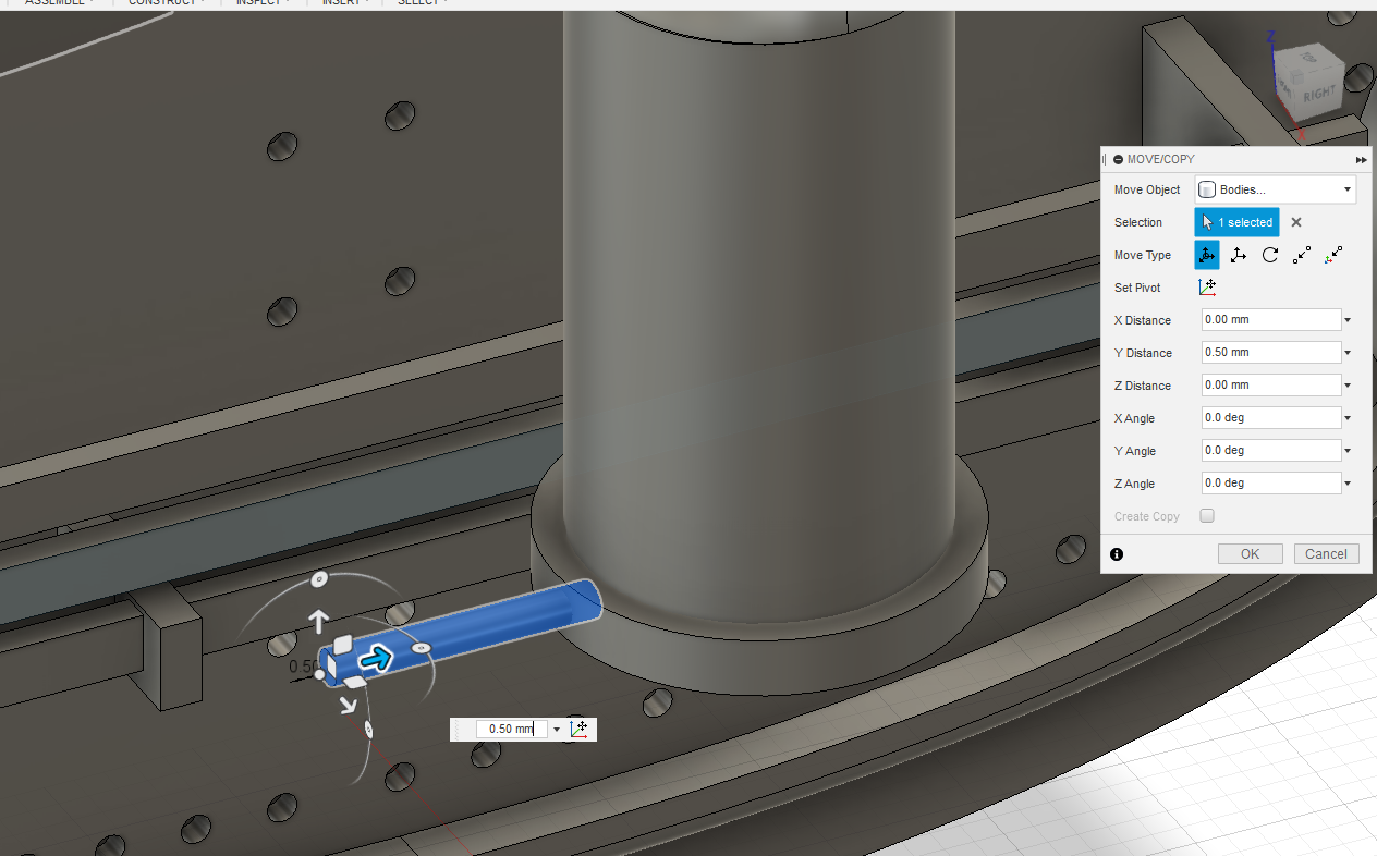
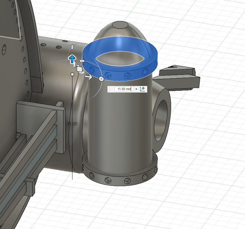
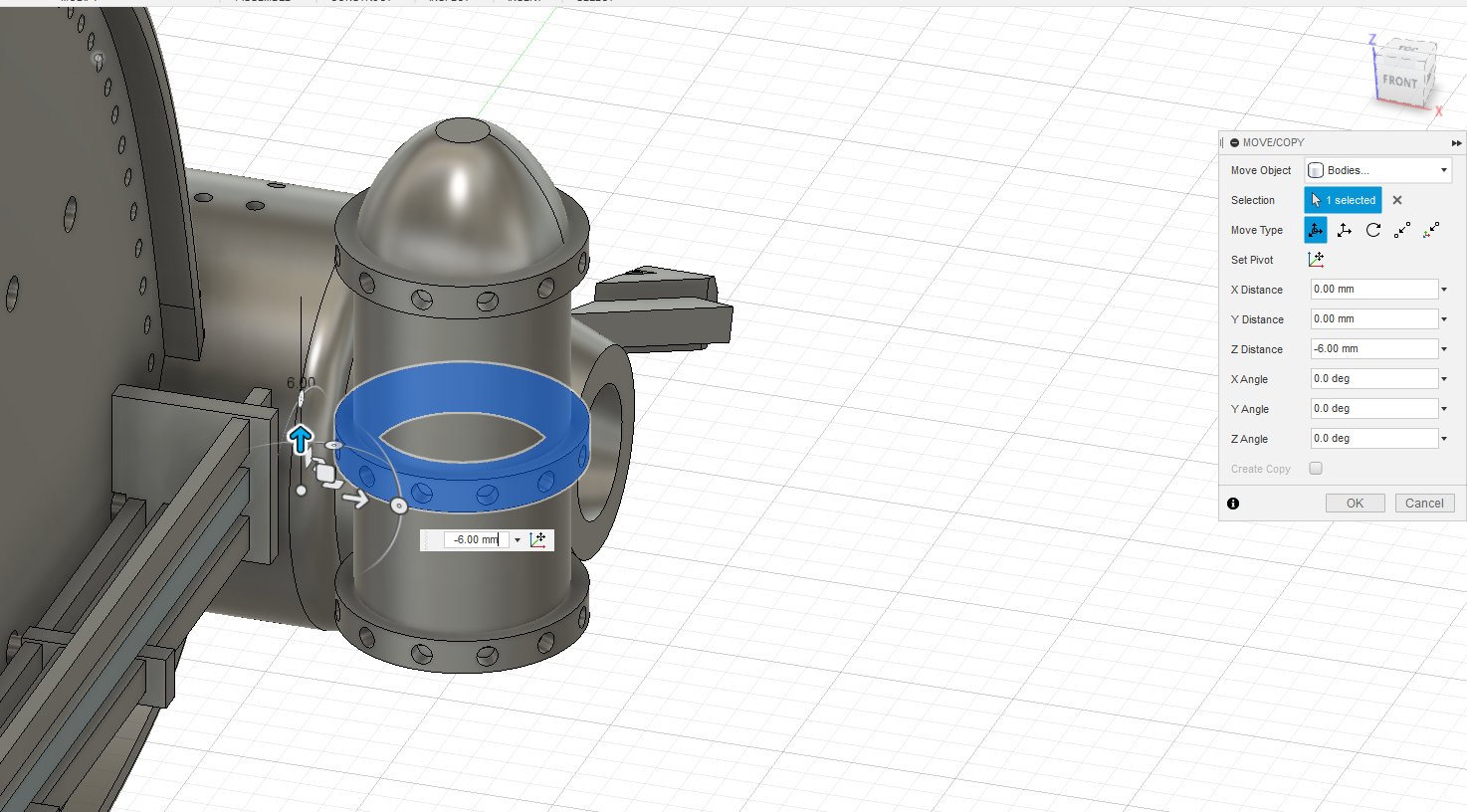
- Select the newly created cylinder and type “M” to move it .5 mm into the original object
- Click “OK”
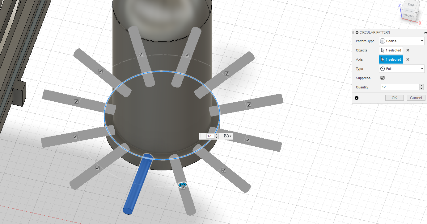
- From the “Create” dropdown, select “Pattern” and “Circular Pattern”
- Select the newly created cylinder and create duplicates along the circle at the edge of the pipe
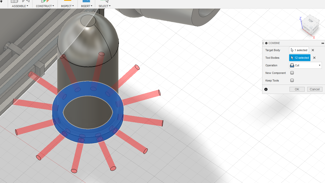
- Under the “Modify” dropdown select “Combine”
- Click the pipe at the bottom of the main cylinder
- Then select each of the newly created cylinders
- Select “Cut” and click “OK” to cut those shapes out of the pipe
- Select the pipe (now containing rivet holes) and type Ctrl+C and Ctrl+V to copy and paste
- Move the new object to the top of the original cylinder
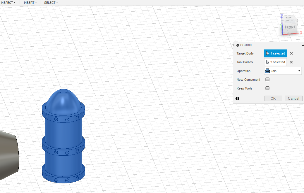
- Right click to the right of the objects and drag to select all
- From “Modify” select “Combine, and join the objects to merge them into one object
- Click the newly merged object to select it
- Right click the object and click “Save as STL”
So, there you have it. You now have the basic tools you need to start creating your own models and hopefully you can see that the process isn’t nearly as daunting as some people think. As with any skill, practice makes perfect and there are plenty of other functions available in Fusion 360, which I may cover in future tutorials. However, you can create some pretty impressive designs just using the basic process of creating sketches and manipulating objects. If you enjoyed this tutorial and want to see some of my models, check out my Instagram, where I share pictures of my designs and prints as well as painting tips.
Subscribe to Our Email Newsletter
Stay up-to-date on all the latest news from the 3D printing industry and receive information and offers from third party vendors.
Print Services
Upload your 3D Models and get them printed quickly and efficiently.


You May Also Like
APAC’s 3D Printing Capital Wave Is Bigger Than Venture Funding
By the usual measure, a tally of funding rounds, APAC’s additive manufacturing market had a quiet second quarter. The capital that has actually closed across the region comes to about...
HP Stock Jumps on 3D Printing Buzz
HP (NYSE: HPQ) had its best day in over a year this week, with shares jumping more than 7% on Tuesday. Interestingly, the move was quickly tied to 3D printing,...
3D Printing News Briefs, April 8, 2026: LiDAR Scanning, Vapor Smoothing, FDM Optimization, & More
We’ll kick off today’s 3D Printing News Briefs with some 3D scanning news from Artec 3D, and then move on to new America Makes Project Calls. Then, Raise3D and AMT...
3D Printing Market Hits $16B in 2025 as Growth Picks Up Again
The global 3D printing market reached $16 billion in 2025, growing just over 10% year over year, according to new data from Additive Manufacturing Research (AM Research). After a slower...