
University of Auckland: Growth-Induced Bending of 3D Printed Samples Based on PET-RAFT Polymerization

4D printed objects are 3D printed objects made with smart materials that respond to environmental stimuli, like liquid and heat, or return to an original form after deformation. Researchers from the University of Auckland published a paper regarding 3D printing and growth-induced bending based on photo electron/energy transfer reversible addition-fragmentation chain-transfer (PET-RAFT) polymerization.
By adding reversible deactivation radical polymerization (RDRP) constituents to a 3D printed structure to create “living” materials, which keep polymerizing on-demand, allows structures to be built with post-production functionality and modularity. But, as the Auckland team states, “this forms only half of the solution.”
RAFT processes have been used as a controlled polymerization technique to help with self-assembling macromolecules and block copolymerization. They previously demonstrated photo-RAFT polymerization 3D printing under several visible wavelengths, showing that a facile surface modification “could be performed on the samples after printing with a range of different monomers.”
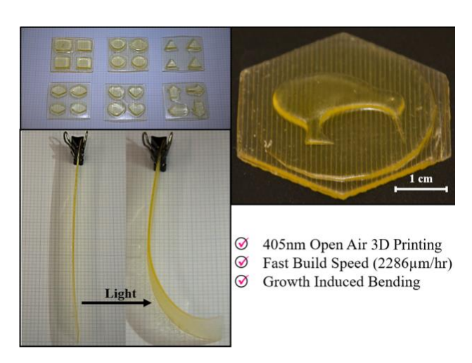
Graphical abstract
“For this work, we further optimized the PET-RAFT 3D printing formulation and demonstrated the 3D printability using a commercial DLP 3D printer with standard 405nm light sources,” they wrote. “We also explore the 4D post-production modification capabilities of the 3D printed object using green light (λmax = 532 nm).”
The PET-RAFT recipe they used, below, adds a tertiary amine and the photo redox catalyst EY, the latter of which “is raised to an excited state (EY*) under irradiation where it then has several pathways to release its energy.” This is useful for 3D printing, since it’s a desirable “oxygen tolerant pathway.”
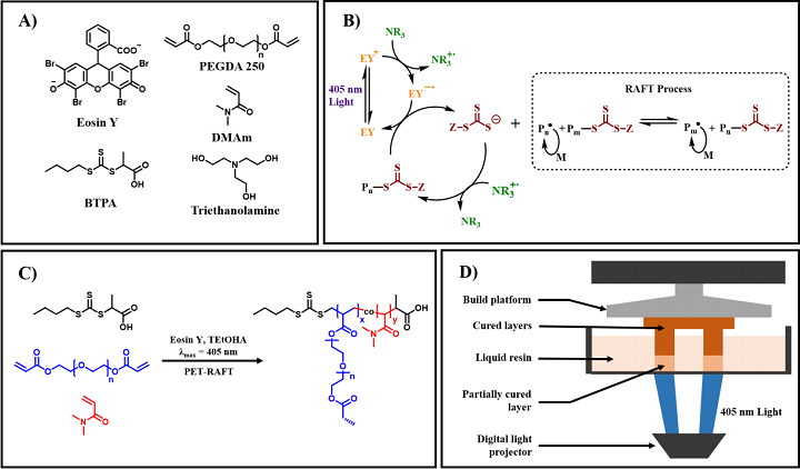
(A) Chemical structures of Eosin Y (EY), 2-(butylthiocarbonothioylthio) propanoic acid (BTPA), poly (ethylene glycol) diacrylate (PEGDA, average Mn = 250 g/mol), N, N-dimethylacrylamide (DMAm), and triethanolamine (TEtOHA). (B) Proposed combined PET-RAFT mechanism showing tertiary amine pathway by Qiao, Boyer, and Nomeir15, 23-25 (C) Reaction scheme for PET-RAFT polymerization of our 3D printing resin. (D) Schematic of a standard DLP 3D printer.
In their previous research, they used a 3D printing resin that was much slower to polymerize, and produced brittle objects. This time, they made several changes to the resin, such as replacing the RAFT agent CDTPA with BTPA and adjusting monomer composition.
“The development of an optimized 3D printing resin formula for use in a commercial DLP printer (λmax = 405nm, 101.86µW/cm2) was the first step in this research. Thus, several criteria were used to determine the quality of the optimized resin; the optimized resin must be able to hold its form in 60 seconds or less exposure time, the printed objects must have a good layer to layer resolution and binding, must be an accurate representation of the CAD model, and the resin must be stable enough to be reusable for consecutive runs,” the team explained.
They kept these criteria in mind while creating and testing new resin recipes with Photo Differential Scanning Calorimetry (Photo-DSC) and a 400-500 nm light source range.
“A monomer to RAFT agent ratio of 500:1 was chosen as a balance between a faster build speed, and a high enough RAFT concentration to perform post-production modifications,” they said. “For the first step in optimization we decided to compare two asymmetric RAFT agents, CDTPA and BTPA.”
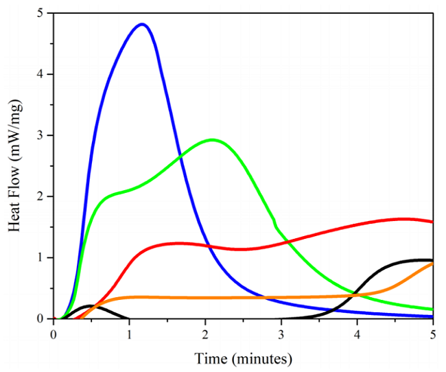
Photo-DSC plot showing resin composition of [BTPA]: [PEGDA]: [EY]: [TEtOHA] = 1:500:0.01:20 (blue), [BTPA]: [PEGDA]: [DMAm]: [EY]: [TEtOHA] = 1:350:150:0.01:20 (green), [BTPA]: [PEGDA]: [DMAm]: [EY]: [TEtOHA] = 1:150:350:0.01:20 (red), [CDTPA]: [PEGDA]: [EY]: [TEOHA] = 1:500:0.01:20 (black), and [CDTPA]:[PEGDA]:[EY]:[TEA] = 1:200:0.01:2 (orange) form our previous PET-RAFT work, were compared to find an optimum new resin formula. The effects of different RAFT agent and comonomer ratio are noticeable on the maximum heat flow and the peak position of tmax.
The first formula, [BTPA]: [PEGDA]: [EY]: [TEtOHA] = 1:500:0.01:20, had a limited inhibition period, while [CDTPA]: [PEGDA]: [EY]: [TEtOHA] = 1:500:0.01:20 had a longer one.
“These results help to demonstrate the increase in polymerization rate that can be achieved by using BTPA in place of CDTPA,” they noted.
Because of its high glass transition temperature, DMAm was added as a comonomer in [PEGDA]: [DMAm] = 70:30 and 30:70 ratios. This slowed the polymerization rate for the resin formulas [BTPA]: [PEGDA]: [DMAm]: [EY]: [TEtOHA] = 1:350:150:0.01:20 and [BTPA]: [PEGDA]: [DMAm]: [EY]: [TEtOHA] = 1:150:350:0.01:20, but it was still faster than the CDTPA formulation. The researchers used this formulation to 3D print samples for dynamic mechanical analysis (DMA) and 4D post-production modification.
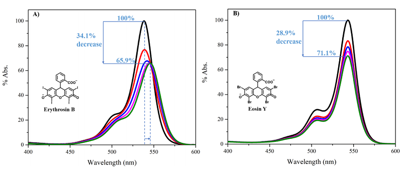
UV-Vis absorption spectra; (A) EB under 405nm (397.45µW/cm2) exposure for; initial (black), 10 (red), 20 (blue), 30 (magenta) and 40 minutes (olive). (B) EY under 405nm exposure for; initial, 10, 20, 30 and 40 minutes.
It’s important that photocatalysts don’t have issues like photobleaching or photodegradation during a photocatalytic process. Above, you can see a comparison in absorbance loss between organic photocatalysts EY and Erythrosin B (EB), “using their absorbance curves after different periods of 405 nm light irradiation.”
“Both showed a noticeable gradual decrease in UV absorbance which could likely be due to irreversible photodegradation, given that the effect remains after the sample has been stored overnight in a dark environment and measured again,” the team explained.
After longer periods of time, the EB solution started changing color, but this didn’t happen with the EY formulation, which is why the team kept it in their 3D-RAFT resin composition. A photostable catalyst, like EY, makes it possible for the 3D printing process to continue undisturbed.
The 3D printed samples that underwent DMA analysis were:
- optimized RAFT resin before and after post-production modification
- non-3D printed DMA sample by PET-RAFT polymerization in bulk
- 3D printed free radical polymerization (FRP) control sample
The first type were 3D printed with a 30 µm thickness, a 60 second attachment time, and 30 seconds of exposure per each of the 53 layers. The second was fabricated with the same optimized formula “but polymerized in bulk using an external mold and a conventional 405nm lamp external,” while the FRP samples were printed with the same monomer composition and parameters but used a “conventional photoinitiator, phenylbis (2, 4, 6-trimethylbenzoyl) phosphine oxide (TPO).”

DMA plot showing (black) storage modulus (E’) and (black dashed) Tan δ from 3D printed DMA sample by normal FRP of resin formula [PEGDA]: [DMAm]: [TPO] = 350:150 and 2wt% TPO; (blue) the E’ and (blue dashed) Tan δ from 3D-RAFT printed DMA sample using resin formula [BTPA] :[PEGDA]: [DMAm]: [EY]: [TEtOHA] = 1:350:150:0.01:20; (green) the E’ and (green dashed) Tan δ from the post-print modified DMA sample; lastly (red) the E’ and (red dashed) Tan δ from the non-3D printed DMA sample prepared by normal PET-RAFT polymerization in bulk.
A temperature ramp (2˚C/min) was performed in order to find the storage modulus (E’) and glass transition temperature (Tg) of the samples, and there was a major change “in the E’ to 80 MPa and Tg to 15˚C” when the samples were compared to ones that weren’t 3D printed but instead polymerized in a mold.
“This layer-by-layer construction appeared to play a major role in the E’ at room temperature of the overall sample,” the team noted. “Each layer in the 3D printed sample received equal light irradiation (apart from attachment layer where specified), whereas in the bulk samples light had to penetrate through the entire thickness of the resin.”
Samples printed with RAFT resin had methyl methacrylate (MMA) monomer inserted post-production “in a growth medium devoid of solvent,” and DMA was used to analyze the effect of this modification on the prints’ mechanical properties, as well as “the relative effect on E’ and Tg of the sample.”
“The E’ at room temperature of the sample had decreased to 100 MPa but the Tg remained constant at about 19˚C,” they explained. “These limited changes can largely be attributed to the fact that BTPA is an asymmetric RAFT agent, all the growth being surface focused thus limiting the mechanical effects on the 3D printed RAFT sample.”
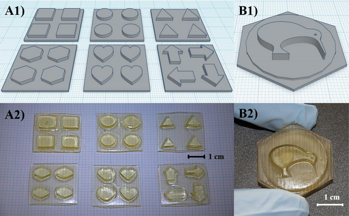
A1) CAD model for shapes upon 3 × 3 cm base. A2) Corresponding 3D-RAFT objects printed using DLP 3D printer. B1) Kiwi bird CAD model upon tiered base. B2) Corresponding 3D-RAFT printed object.
Once they determined the optimal RAFT 3D printing resin, the researchers designed CAD models for the objects they would print. They arranged different shapes, like triangles and Kiwi birds, on top of square and hexagonal base plates and circular coins, in order to see how the PET-RAFT resin formulation could handle features like corners and curves.
“These objects generally represented an accurate 3D print of the corresponding CAD model, confirming that the current 3D-RAFT resin was capable of printing 3D objects using a 405nm DLP 3D printer (λmax = 405 nm, 101.86µW/cm2),” they noted.
“Objects printed with 3D-RAFT also displayed an actual build speed of 2286 µm/hr (calculated from the actual height of printed objects over the full print time) consistent with that of the theoretical build speed, which is significantly faster than our previous PET-RAFT resin formula…”
Only limited shrinkage occurred on these prints, and after being washed for two days each in ethanol, THF, and DMSO, the team did not note a visible loss in yellow “arising from the trithiocarbonate group of the RAFT agent.” The 3D-RAFT resin was also reusable over more than ten prints.
“Having demonstrated that we could reliably print objects using our new RAFT resin, we endeavoured to demonstrate that these objects had retained their desired “living” behavior and could undergo post-production modification,” the team wrote.
They immersed half of a 3D-RAFT printed strip in a growth medium containing [BA]: [EY]: [TEtOHA] = 500:0.01:20 in DMSO. Then, a green 532 nm LED light was directed onto one of its faces, and after 15 minutes, “the strip showed moderate curvature.” They could see the strip was bending considerably after 15 more minutes, and it was also much softer, with the irradiated face paler than the other, and the growth medium was cloudier.

Optical images and graphical representations of growth-induced bending process. (A) The initial 3D-RAFT printed strip. (B) 3D-RAFT strip after 15 minutes monodirectional green light irradiation (532nm, 58.72µW/cm2) in a growth medium of DMSO and BA. (C) The same strip after 30 minutes monodirectional green light irradiation in the same growth medium. (D) Reaction scheme for the photo-catalyzed insertion of BA monomer under green light irradiation.
They next performed some control experiments. First, they tried the same thing with an FRP printed strip and a [PEGDA]: [DMAm] = 350:150 and 2wt% TPO growth medium, but this did not bend. A 3D-RAFT printed strip was left to soak in the original growth medium, without any light irradiation, for 24 hours, “to ensure that the bending was coming from growth rather than an alternate stimulus such as solvent swelling,” and saw no changes. Finally, they tried the same original process to return the bent 3D-RAFT strip back to its original form by shining the green light at it from the opposite direction. While it ultimately worked, it took three hours of irradiation to bend the strip back, which “indicates the unfavorability of introducing stress on the opposing side of the strip by our current methods.”
“To the best of our knowledge, this is the first demonstration of the growth of new material into the surface of an existing 3D printed object using RAFT polymerization to induce a bending response,” they concluded.
“In summary, we have further developed a 3D printable RAFT resin formula with an improved build speed up to 2286 µm/hr and demonstrated its ability to undergo 4D post-production transformation. We first demonstrated a facile method for growth induced bending of 3D-RAFT printed strips which opens an alternative pathway for movement and modification of these printed objects.”
Discuss this and other 3D printing topics at 3DPrintBoard.com or share your thoughts below.
Subscribe to Our Email Newsletter
Stay up-to-date on all the latest news from the 3D printing industry and receive information and offers from third party vendors.
Print Services
Upload your 3D Models and get them printed quickly and efficiently.


You May Also Like
Bambu Lab 3D Prints Miniature Playground City for Kids in China
Bambu Lab has partnered with meland to open what they describe as China’s first 3D printing creativity center for children. The new space, officially named “meland x Bambu Lab,” launched...
MIT’s Enterprise Additive Manufacturing Program Heads to RAPID + TCT 2026
MIT will offer the class Enterprise Additive Manufacturing over the course of five days. Three and a half days will take place at MIT, while two half days will see the...
Advancing Workforce Development for Industrial Additive Manufacturing
As additive manufacturing (AM) continues its transition from a niche technology to a core element of industrial production, workforce development has emerged as one of the industry’s most pressing issues....
Stratasys’ Jesse Roitenberg on Why Additive Manufacturing Is Becoming a Basic Skill
After nearly two decades working at Stratasys — and most of that time focused on education — Jesse Roitenberg has seen additive manufacturing (AM) move from novelty to necessity. 3DPrint.com...