
UK Researchers: Single-Droplet Resolution for 3D Printed Functional Synthetic Tissues

Researchers from the UK have completed a unique study in 3D printed networks, releasing their findings in the recently published ‘Controlled packing and single-droplet resolution of 3D-printed functional synthetic tissues.’
The development of synthetic tissues requires accuracy in fabricated structures. Currently, while there are challenges in 3D printing such networks, assembly of such geometries can be effective for the performance of specific tasks. In the face of obstacles that often prevent complex designs and necessary functionality, the research team studied how to balance arrangements of droplets brought together with interface bilayers.
Inspired by the 3D polyhedra of nature, the research team examined the properties and performance resulting from molecules packed into crystal structures, as well as cell arrays found in tissues. Their study even included the structure of honeycombs. Such momentum in research is not new as studies have been precipitated by influences such as nacre (found in shells), natural materials like pinecones, and even mammals like bats.
In this study, the researchers experimented with fabrication concepts bordering on the 4D printing level as they considered how to improve control over deformable ‘spheres,’ allowing them to imitate live tissue.
“In this area, networks of picolitre-sized droplets separated by droplet interface bilayers (DIBs) hold significant promise because of discrete compartmentalization, inherent connectivity, and communication between subunits,” stated the researchers.
Strengthened by the presence of lipids, DIBs are built as aqueous droplets connect in oil and create a bilayer, with networks being created through microfluidics, mechanical manipulation, magnetism, and optical tweezers.
“When aqueous droplets pack in 3D, each makes multiple droplet–droplet contacts (by forming DIBs with its neighbors), resulting in the deformation of the spherical droplets into polyhedral,” stated the researchers.
The science of building such networks does require thorough comprehension of how printing parameters affect droplet deformation:
“At present, for example, the occurrence of printing defects dictates that conductive signaling pathways in large networks (>100 droplets) must be designed to be more than 2–3 droplets wide to ensure continuity,” stated the researchers. “However, single-droplet-wide signaling pathways would be feasible if synthetic tissues could be patterned at single-droplet resolution.”
Previously, researchers have explored deformation of droplets in oil and water mixtures, including the fabrication of microfluidic systems for experimenting with drops in 2D sheets—as well as studying clusters that self-organize while flowing. Noted as most helpful to their own research, studies by Princen et al. focused on the value of contact angles between droplet packing in both 2D and 3D. In this study, the researchers experimented with hexagonal close-packed (hcp) lattices from hundreds of 3D-printed picolitre-sized droplets, as well as using automation to fabricate synthetic tissues with single droplets.

a Schematic of a pair of aqueous droplets forming a droplet interface bilayer (DIB) in a lipid-in-oil solution, and the definition of the equilibrium contact angle (θDIB). b–e Bright-field and fluorescence microscopy overlays of droplet pairs formed with 1 mM DPhPC and φSIL values of 0.20 (θDIB = 6.0 ± 0.7°) (b), 0.50 (θDIB = 26.5 ± 1.7°) (c), 0.80 (θDIB = 53.4 ± 0.8°) (d) and with 1 mM POPC and φSIL = 0.65 (θDIB = 85.3 ± 3.8°) (e). Scale bars = 150 µm. In each image, the right droplet contains 10 µM Atto488 to demonstrate that a bilayer has formed and compartmentalises the bilayer-impermeant dye. f A plot showing the linear dependence of θDIB with respect to φSIL for 1 mM DPhPC (linear regression R2 = 0.99) (see Supplementary Table 1). g A plot showing the linear dependence of θDIB with respect to xPOPC at φSIL = 0.65 (linear regression R2 = 0.99) (see Supplementary Table 2). h A plot of the 2D linear dependence of θDIB with respect to both φSIL and xPOPC (regression plane R2 = 0.99) (see Supplementary Table 8). The total lipid concentration was 1 mM. Data points that lie above and below the regression plane are in magenta and cyan, respectively. For all experiments, the aqueous phase was PBS at pH 7.2. Each data point in f–h is the mean of n > 3 contact angle measurements, and the error bars represent the standard deviation. When error bars are not visible, they have standard deviations smaller than the data symbols. (For individual n values, see Supplementary Table 24.)
Using a 3D printer built in their own lab, the researchers explored structures via 3D droplet networks with hundreds of droplets included (PBS, 100 µm diameter, ≈524 pL volume). Each network required 224 droplets at droplet ejection frequency of 0.5 s−1. Overall, 129 printed networks were evaluated, resulting in two major arrangements: hexagonal close-packed (hcp) and body-centre cubic (bcc). They also categorized irregular packing as either ‘amorphous’ or ‘not packed.’
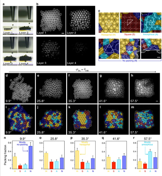
a Images of a 3D-printed droplet network (7 × 8 × 4 droplets in x, y and z directions) as each layer (1 to 4) is formed. b Horizontal cross-sections of layer 1 (bottom), layer 2, layer 3 and layer 4 of a droplet network imaged by confocal microscopy. Lipid bilayers and monolayers are visualized with Atto550M. c Examples of packing types in the first layer of 3D-printed networks. Our classification method draws triangles (indicated by black and highlighted white triangles) between the centers of three neighboring droplets and assigns the local packing type of each triplet based on the triangle geometry (Delaunay triangulation). Droplet triplets are classified as packed in a hexagonal (yellow), square (red) or amorphous (cyan) fashion, or not packed (blue) (see “Methods”). d–m Confocal microscopy images (d–h) and overlays of the packing analysis based on Delaunay triangulation (i–m) of the first layer of 3D-printed droplet networks at increasing φSIL values (corresponding to increasing θDIB). Yellow, red, cyan, and blue triangles represent the packing types defined as hexagonal, square, amorphous, and no packing, respectively. Scale bar = 100 µm. n–r Quantification of hexagonal (yellow), square (red), amorphous (cyan) and no-packing (blue) area fractions in the first layer of 3D-printed droplet networks at increasing values of φSIL. In n–r, each bar is the mean of n > 3 networks (see Supplementary Table 21 for individual n values and Supplementary Fig. 3); error bars represent the standard deviation.
Results offered three θDIB-dependent situations:
- θDIB << θc, droplet networks pack loosely with the greatest amount of no packing
- θDIB >> θc, droplet networks pack tightly and are distorted, with the greatest amount of amorphous packing
- θDIB ≈ θc, droplet networks show the greatest amount of hexagonal packing

For all conditions in a–e, θDIB = 36.3° (calculated from Eq. (1)). The φSIL and xPOPC values in b–d are φSIL = 0.60 and xPOPC = 0.00 (cyan), φSIL = 0.55 and xPOPC = 0.13 (purple), and φSIL = 0.52 and xPOPC = 0.20 (magenta). a Optical microscopy images of two droplets (75 nL) forming a DIB after contact. The non-equilibrium contact angle (θ) increases with time (0–900 s) until the equilibrium contact angle (θDIB) is reached (t = 1800 s). Scale bar = 150 µm. The images correspond to timepoints along the purple profile in b. b Plots of θ versus time for droplet pairs. Plots are the mean of n = 5 repeats for each condition, and error bars represent the standard deviation. The grey dashed lines correspond to timepoints relevant to printing 3D droplet networks: tfast (0.50 s), tdrop (2.00 s) and tslow (4.00 s) indicate the time intervals between consecutive printed droplets at fast (tfast−1 = 2.00 s−1), standard (tdrop−1 = 0.50 s−1), and slow (tslow−1 = 0.25 s−1) printing frequencies; tlayer (225 s) is the time it takes to print a single layer at a printing frequency of 0.50 s−1. c A bar chart of the hexagonal packing area fraction of 3D droplet networks printed at a droplet ejection frequency of 0.50 s−1. The hexagonal area fraction under the purple condition was significantly greater than for the other two conditions (one-way ANOVA with Tukey’s multiple comparison test) (see Supplementary Table 15). d Plots of hexagonal packing area fractions in the first layers of 3D droplet networks generated at different printing frequencies (fD). The frequencies marked in grey are the inverse of the timepoints marked in b (i.e., fD = tD−1, where tD is the time interval between the ejection of two consecutive droplets). For statistical tests, see Supplementary Table 16. e A confocal microscopy image and overlay of Delaunay triangulation of the first layer in a 3D-printed droplet network (7 × 8 × 4; x, y, z) at φSIL = 0.55 and xPOPC = 0.13 (purple condition in b–d) at a printing frequency of 0.50 s−1. Scale bar = 100 µm. Each data point in the graphs c and d is the mean of n > 3 repeats, and error bars represent the standard deviation. *, ** and *** indicate p-value <0.05, 0.01 and 0.001, respectively. For individual n values, see Supplementary Tables 22 and 23.
With 1-palmitoyl-2-oleoyl-sn-glycero-3-phosphocholine (POPC) added to the lipids, contact angle equilibration was rapid initially, but followed by a slower phase. The study confirmed that:
“… the regularity of the hcp in 3D-printed droplet networks was optimal when θDIB ≈ θc, and also when the printing frequency and the kinetics of DIB formation were matched to allow the initial formation of regular 2D hexagonal packing in the first layer, which then templated hcp when subsequent layers were printed on top.”
For hcp regions, space-filling trapezo-rhombic dodecahedra were formed, consisting of 12 DIBs and peripheral droplets.
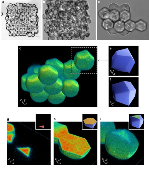
a–c Bright-field microscopy images of a 3D-printed droplet network (10 × 12 × 4; x, y, z) (1 mM DPhPC, φSIL = 0.60, and a calculated θDIB = 36.3° from Supplementary Fig. 5b) comprising an aqueous phase of 20% (w/v) poly(ethylene glycol) diacrylate, 0.5% (w/v) Irgacure 2959 (photo-initiator), 100 µM ethidium bromide-N,N’-bisacrylamide (photo-cross-linkable fluorophore), and PBS, before (a) and after (b) photo-polymerisation with UV light. Scale bars = 100 µm. c An image of an hcp cluster of hydrogel polyhedra dispersed in PBS. Scale bar = 25 µm. d 3D reconstruction of droplet shapes from confocal microscopy of the hcp region in c, which contained 14 clustered droplets (Supplementary Movie 1). e, f A computer model of a trapezo-rhombic dodecahedron—the space-filling polyhedron of hexagonal close packing—viewed from below (e) (compare the white box in d) and above (f). g–i A droplet sectioned through the z-axis from bottom to top, with (inset) computer models of trapezo-rhombic dodecahedra showing 2D sections of three-fold (g, i) and six-fold (h) symmetry.
“Our findings are applicable to any other assemblies of compartmentalized systems—such as adhesive giant uni-lamellar vesicles or protein compartments—in which structural order is required to build synthetic tissues with precise functionalities,” concluded the research team, confirming that they can 3D print droplet networks with complex designs, and at high resolution—like tubular structures.
“This level of precision was not achieved at the periphery of the 3D printed constructs, where most printing defects and irregular arrangements of droplets were confined. However, our observations also suggest that regular packing at the periphery of 3D-printed droplet networks might be further improved by ‘annealing’ steps after the printing process (i.e., cyclical decrease and increase in contact angles), or by templating the droplet packing lattice using patterned surfaces.”
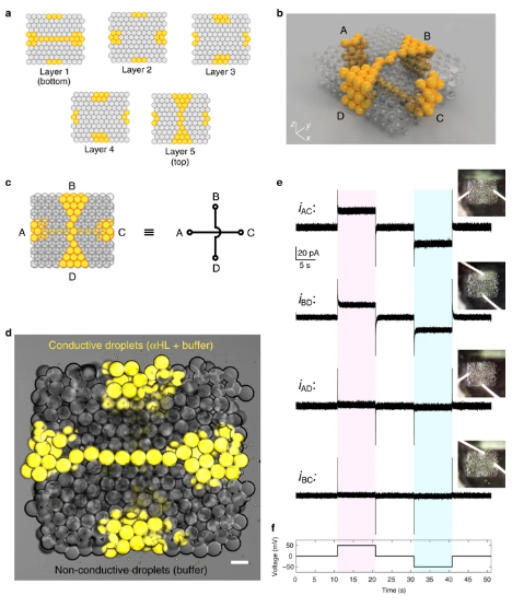
a Maps of the first (bottom), second, third, fourth and fifth (top) layers of a 3D-printed synthetic tissue in which two conductive, single-droplet-wide pathways containing αHL (in yellow) are patterned in 3D within a network of non-conductive droplets (in grey). b A computer model displaying the 3D architecture of the synthetic tissue. The two single-droplet-wide pathways span the synthetic tissue, one horizontally at the bottom (connecting A to C), and one vertically at the top (connecting B to D) of the network. c Simplified diagram of the synthetic tissue, and equivalent circuit model. d Bright-field and fluorescent microscopy overlay of the synthetic tissue. Droplets in the single-droplet-wide conductive pathways contained α-hemolysin (60 µg mL−1), 25 mM Tris-HCl (pH 7.6), 1 M NaCl and 10 µM Atto488 fluorophore (false coloured in yellow). Scale bar = 100 µm. e Electrical recordings of the ionic currents flowing through the two single-droplet-wide conductive pathways connecting A to C (iAC) and B to D (iBD) upon application of the voltage protocol shown in f. When a potential of ± 50 mV was applied, changes in ionic currents of +25.6 ± 1.4 pA (at positive potential) and −25.6 ± 1.5 pA (at negative potential) were observed for iAC, and of +19.4 ± 1.2 pA (at positive potential) and −19.8 ± 1.3 pA (at negative potential) for iBD. Conversely, we recorded non-significant changes in ionic current for the same applied potentials between A and D (iAD) or B and C (iBC). iAD: +1.8 ± 1.3 pA and −1.8 ± 1.4 pA (at positive and negative potentials respectively); iBC: +0.9 ± 1.1 pA and −0.9 ± 1.1 pA (at positive and negative potentials, respectively).
What do you think of this news? Let us know your thoughts! Join the discussion of this and other 3D printing topics at 3DPrintBoard.com.
[Source / Images: ‘Controlled packing and single-droplet resolution of 3D-printed functional synthetic tissues’]Subscribe to Our Email Newsletter
Stay up-to-date on all the latest news from the 3D printing industry and receive information and offers from third party vendors.
Print Services
Upload your 3D Models and get them printed quickly and efficiently.


You May Also Like
Heating Up: 3D Systems’ Scott Green Discusses 3D Printing’s Potential in the Data Center Industry
The relentless rise of NVIDIA, the steadily increasing pledges of major private and public investments in national infrastructure projects around the world, and the general cultural obsession with AI have...
3DPOD 260: John Hart on VulcanForms, MIT, Desktop Metal and More
John Hart is a Professor at MIT; he´s also the director of the Laboratory for Manufacturing and Productivity as well as the director of the Center for Advanced Production Technologies....
Etsy Design Rule Change Reduces Selection of 3D Printed Goods
Online marketplace Etsy has implemented a rule change requiring all 3D printed goods on the site to be original designs. The update to the site’s Creativity Standards states, ¨Items produced using...
E-Beam OEM Wayland Additive Partners with USC Racing to 3D Print Titanium Exhaust Collector
Every year, standards organization SAE International holds a competition called Formula SAE, in which students from both undergraduate and graduate programs design, build, and race small formula-style race cars. For...