Barcelona: Electrostatic Jet Deflection for Ultrafast 3D Printing


Barcelona researchers Ievgenii Liashenko, Joan Rosell-Llompart, and Andreu Cabot have come together to author the recently published, ‘Ultrafast 3D printing with submicrometer features using electrostatic jet deflection.’ Following the continued trend for improving additive manufacturing processes as such technology begins to play an increasingly important role around the world—whether in industries like auto, aerospace, or medical—the authors focus on expanding the limits of production and performance of electrohydrodynamic jetting.
A common thread runs through many research papers today, regarding the immense benefits of 3D printing and additive manufacturing, but also the many challenges that still exist for users on any level. The research team points out that there are still ‘important limitations’ on the following:
- Production speed
- Availability and combination of materials
- Control over microstructure and functionality
“Additionally, the cost and complexity of manufacturing equipment that enables producing submicrometer features are prohibitive for a true distributed production,” note the authors.
Nozzle-based 3D printing does offer affordability and simplicity, however, allowing for fabrication of ‘virtually any substance,’ to include polymers, metals, ceramics, wood, and of course a variety of different elements associated with bioprinting and tissue engineering:
“Such unmatched material versatility stems from the use of metal or polymer melts or solvent-based inks, which can be formulated to contain any component in the form of ions, molecules, nanoparticles, or even living cells,” stated the authors.
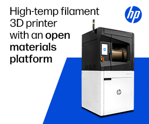
The electrostatic control of the jet trajectory. a Optical photographs of the nozzle, ink drop (below dotted line), Taylor cone, and the electrified jet generated by applying 1000 V between the nozzle and a printing substrate (not shown). Scale bars: 500 µm and 50 µm. b Schematic of an EHD 3D printer with jet-deflecting electrodes. c Set of jet-deflecting electrodes and needle used as nozzle. Scale bar: 5 mm. d Simulation of the electric potential and field around the jet in the presence of a jet-deflecting electrode. The deflecting electrode, nozzle and ink drop are shown in white for clarity but are at the specified potentials. The electric field streamline (also in white) starting at the tip of Taylor cone represents the theoretical trajectory of a massless jet. Additional simulation results can be found in the supplementary material, Supplementary Fig. 1 and Supplementary Movie 3. e High-speed video captures of the jet being deflected in 1D with a frequency of 100 Hz (video showing jet deflection at 10, 50 and 100 Hz can be found in the supplementary material, Supplementary Movie 1). Two jet-deflecting electrodes (not shown) were used, positioned on the left and on the right side of the video captures. Video captures show the nozzle, the Taylor cone at the end of the ink drop and the thin jet expelled. The trajectory of this jet and thus its point of arrival to the substrate were modulated by the voltage applied to the jet-deflecting electrodes. Scale bar: 500 µm
Electrohydrodynamic (EHD) jetting offers unique benefits to users seeking high resolution 3D printing, eliminating nozzle clogging, allowing for the use of many different inks, and with viscosities ‘ranging over several orders of magnitude.’ There are still serious challenges though in meeting the massive accelerations required for speed while fabricating small and complex geometries.
The researchers aimed to ‘unleash the potential of high-speed printing’ by deflecting the jet trajectory, thus controlling continuous electrified jets affecting the printing substrate.
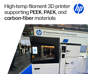
Role of jet deflection parameters. a Optical photographs of the PEO fiber collected as the substrate is moved at 1 mm s−1 and the jet is deflected with a frequency of 100 Hz. The stepwise increase of amplitude of the jet deflection signal resulted in a stepwise increase of width of the PEO pattern, fiber straightening and alignment. The amplitude of the jet deflection was varied from 200 V to 2000 V as depicted in the micrographs and the two electrodes were located at 10 mm from the default jet trajectory. Scale bars are 200 µm on main panel and 25 µm on magnified panels. b Dependence of the width of the printed pattern on the signal amplitude at a fixed frequency of 100 Hz. The blue shaded area displays the amplitude range where fiber buckling would be obtained at this fixed frequency. The four points in red correspond to the four amplitudes experimentally tested and presented in a. At the lowest amplitude that provides straight fibers, the printing speed and the jet speed are matched (point D) and the jet speed can be computed as a product of the fiber length printed in one deflection period times the printing frequency. At this amplitude, the width of the printed pattern reaches a plateau and it cannot be increased by increasing the signal amplitude. c Experimental dependence of the jet deflection angle on the jet deflection frequency for two different jet deflection amplitudes, 200 V and 400 V (two opposing electrodes located at 3 mm from the default jet trajectory). A blue line corresponding to a jet deflection speed of 0.5 m s−1 is also plotted. The blued shaded area displays the region providing a jet deflection speed below 0.5 m s−1 , thus jets traveling at this speed would result in fiber buckling. Error bars were determined using the standard error of the mean of five or more measurements.
The authors used a traditional EHD printer; however, they customized the hardware by surrounding the jet with added electrodes for modification of the electric field.
“The voltages at these electrodes were synchronized and produced by amplifying a computer-generated signal in a range from about −2000 V to about 2000 V,” explained the authors. “The movement and position of the XY mechanical stage supporting the printing substrate was also controlled and synchronized through the same computer.”
Fiber length proved to be insufficient when patterns were printed more rapidly than the jet speed as it arrived at the substrate. As a solution, the researchers sought improved parameters, ‘easily accomplished’ with a different calibration pattern.

Printing 2D patterns. a–c Schematics (top panels) and optical photographs of the experimental PEO-PEDOT:PSS patterns printed as the substrate is continuously moved in a straight line (bottom): a fiber buckling obtained with no jet deflection; b sawtooth pattern obtained using 1D jet deflection in an axis normal to the translation of the mechanical stage; and c circular pattern obtained using 2D jet deflection. All optical images have the same scale of 250 µm. d, e Optical photographs of more complex 2D patterns printed using two jet-deflecting electrodes to define the pattern and the mechanical stage to translate the substrate between printing events. A 4.7 wt% PEO ink containing Ag NPs was used to print these patterns. Scale bars (d, e): 1 mm.
“Ultimately, the range of printable materials is only constrained by the requirement that the ink has proper electrical conductivity and viscoelastic properties to flow and prevent its capillary breakup,” explained the researchers. “Therefore, except for minor adjustments in formulation, the electrostatic jet deflection strategy can be extended to produce 3D objects from any of the materials that have already been made into fibers by electrospinning, including biomaterials and even living cells.”
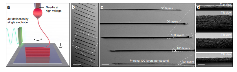
Printing 3D walls. a Schematic of the 3D printing of a wall. b–d SEM micrographs of PEO walls built by layer-by-layer assembly at a jet oscillation frequency of 50 Hz, thus depositing two layers per period. Each wall was printed using exclusively electrostatic jet deflection to position the material on the substrate. The XY translation stage was moved only in between walls. The periodic deflection of the jet during 1.5, 1 and 0.5 s resulted in walls of variable height, composed of 150 layers, 100 layers and 50 layers, respectively. SEM micrographs in d shows the top view of the wall composed of 150 layers and the 45° tilt view of walls composed of 150, 100 and 50 layers. Scale bars (b, c): 200 µm and 50 µm. All SEM micrographs on d have the same scale of 2 µm.
“Through electrostatic deflection of electrified jets, 3D structures of increasing complexity, including crossovers and bridges, were printed by precise electrostatically-driven layer-by-layer self-assembly at frequencies as high as 2000 layers per second,” concluded the authors. “Besides, controlling the ink viscosity and composition allowed adjusting the microstructure of the printed objects. To sum up, we believe that the advantages of EHD jet deflection printing will represent a significant step forward toward ultrafast additive micromanufacturing of 3D objects with virtually any composition and adjusted microstructure and functionality.
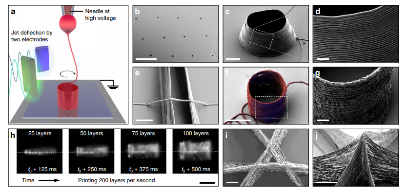
Printing 3D structures. a Schematic of the 3D printing of a cylinder. b–d SEM micrographs at different magnifications of PEO 3D cylindrical microstructures manufactured by EHD jet deflection printing. Scale bars (b–d): 200 µm, 5 µm and 1 µm. e SEM micrograph of a single suspended PEO fiber bridging a gap between 2 parallel nanowalls. Scale bar: 2 µm. f, g SEM micrographs of a PEO-Ag cylindrical structure printed using an ink containing 5 wt% 50 nm Ag nanoparticles. Scale bars: 5 µm and 1 µm. h High-speed video captures displaying the growth of a cylindrical structure at a frequency of 200 Hz. The jet of PEO ink had a diameter of ca. 200 nm and it is invisible on these captures (Supplementary Movie 2). Scale bar: 20 µm. i, j SEM micrographs of the crossing of three walls printed using an ink containing 50 nm Ag nanoparticles, where (i) is a top view of a crossing having a gap of 1 μm and (j) is a tilt view of the peak formed by walls crossing in one point. Scale bars (i, j): 1 µm and 5 µm. SEM micrographs (b–d, f, g, j) were taken with a 40 degree tilt, e with 30 degrees tilt, and (i) with no tilt. High-speed video captures (h) were taken at a shallow angle to the substrate. Image (f) was obtained by superimposing two images taken with secondary electrons and in-lens detectors, where printed fiber was false-colored in red and blue, respectively.
What do you think of this news? Let us know your thoughts! Join the discussion of this and other 3D printing topics at 3DPrintBoard.com.
[Source / Images: ‘Ultrafast 3D printing with submicrometer features using electrostatic jet deflection’]
Subscribe to Our Email Newsletter
Stay up-to-date on all the latest news from the 3D printing industry and receive information and offers from third party vendors.
Print Services
Upload your 3D Models and get them printed quickly and efficiently.


You May Also Like
How One Artist Is Using 3D Printing to Tell Stories About the Ocean
Artist Kimberly Callas sees something different when she looks at a 3D printer. Where others see a machine for making parts, she sees a way to tell stories about the...
Bambu Lab Wants Home 3D Printing to Feel Less Like a Workshop with PLA Pure
As desktop 3D printers become increasingly common in homes, Bambu Lab is focusing attention on something beyond print speed and hardware features. This week, the company launched a new filament,...
AM Asia Watch: China Exported 2.46 Million 3D Printers in Four Months
China’s consumer 3D printer industry seems to be reaching a new level of global dominance. According to Chinese state media outlet China Global Television Network (CGTN), China exported 2.46 million...
Bambu Launches A2L: What the New Printer Reveals About Its Strategy
Bambu Lab continues its relentless march for 3D printing domination with the launch of the A2L. The 330 × 320 × 325 mm printer will have a nozzle temperature of...