Design Guidelines for Direct Metal Laser Sintering, Selective Laser Melting, Laser Powder Bed Fusion


Perchance I came across an excellent document on the design guidelines for Direct Metal Laser Sintering, also called DMLS, Selective Laser Melting, SLM, Laser Powder Bed Fusion and referred to as metal 3D printing. This document was made by UK based design consultancy Crucible Design. Crucible Design was founded in 1990 by Hugh Raymond and Mike Ayre who for the past 28 years have been tackling tough, complex advanced engineering and design projects. Whether working on cost reduction projects or bringing completely new products to market Crucible Design has carefully built up its reputation over the decades. I was so impressed with Crucible’s design guidelines for metal printing document that I asked CEO Mike Ayre if we could republish it here. I also asked him how he came to make it.
The main reason behind my work with metal 3D printing was the SAVING project, which was run by a consortium in 2011 and 2012. The consortium consisted of Exeter University, ourselves, Plunkett Associates, Delcam, EOS and Simpleware. The point of the project was to find ways to use additive manufacturing to reduce energy use. As the processes themselves are so energy intensive, we soon concluded that the only way to achieve the objective was through the use of the parts, not their manufacture. This is where the airline buckle project came from – reducing the weight of the plane to minimise fuel wastage.
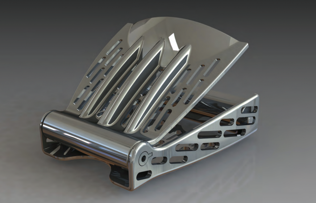
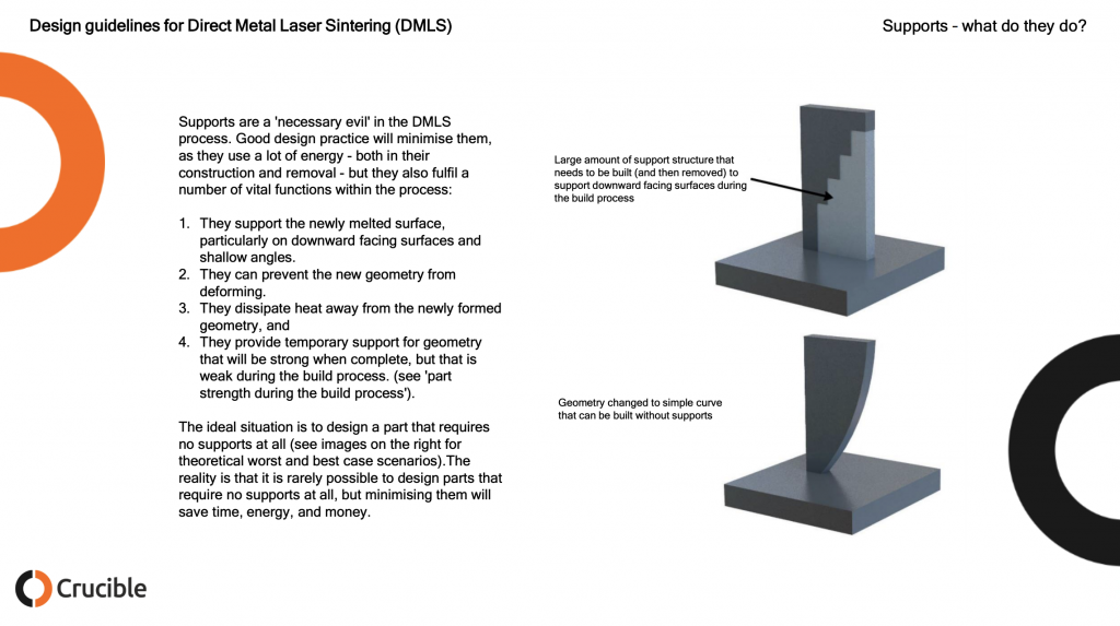
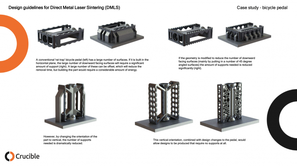
The main problem with metal 3D printing was the same as all design approaches to additive manufacture: early promoters pushed the idea that there were no design limitations, and we ‘were only limited by our imagination’. In fact, this proved to be completely wrong, with 3D printing just having different limitations to conventional methods. In terms of metal printing, the main one is the need to machine out the support structures that are required for any downward facing horizontal surface (the kind of thing that can be washed away using and FDM machine). This requires any efficient design to adopt almost medieval approaches to design, with pointed arches and sloping surfaces that can be built without supports.
Why did you make the guide?
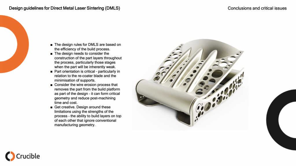
The main reason for making the guide was to inform designers of some of the basic rules and encourage a more creative approach to the use of 3D metal printing and additive manufacture in general. It has been good to see that, since it was written, there is a lot more discussion about appropriate design methods for additive manufacture.
Now the guide was published in 2015 which is eons in 3D printing land. However, the same process limitations and design rules persist. I’ve made design guidelines and design rules documents before and was super impressed with how clear and concise this one was. I think that this is a very valuable resource to people in metal printing today either to learn about designing for metal 3D printing or to use as a teaching aid to help others. If you’re in a design project with a customer then this is also super helpful in trying to let them see that “complexity is free only in dreams.” I am absolutely certain that these images will be spread far and wide, do please credit Crucible Design for their hard work, be mindful that these images are still their copyright and reach out to them should you need any 3D printing design services done. The images below are all Crucible’s the comments are mine.
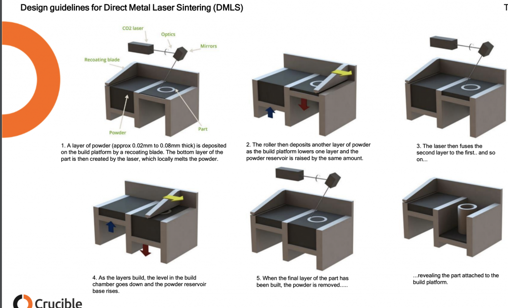
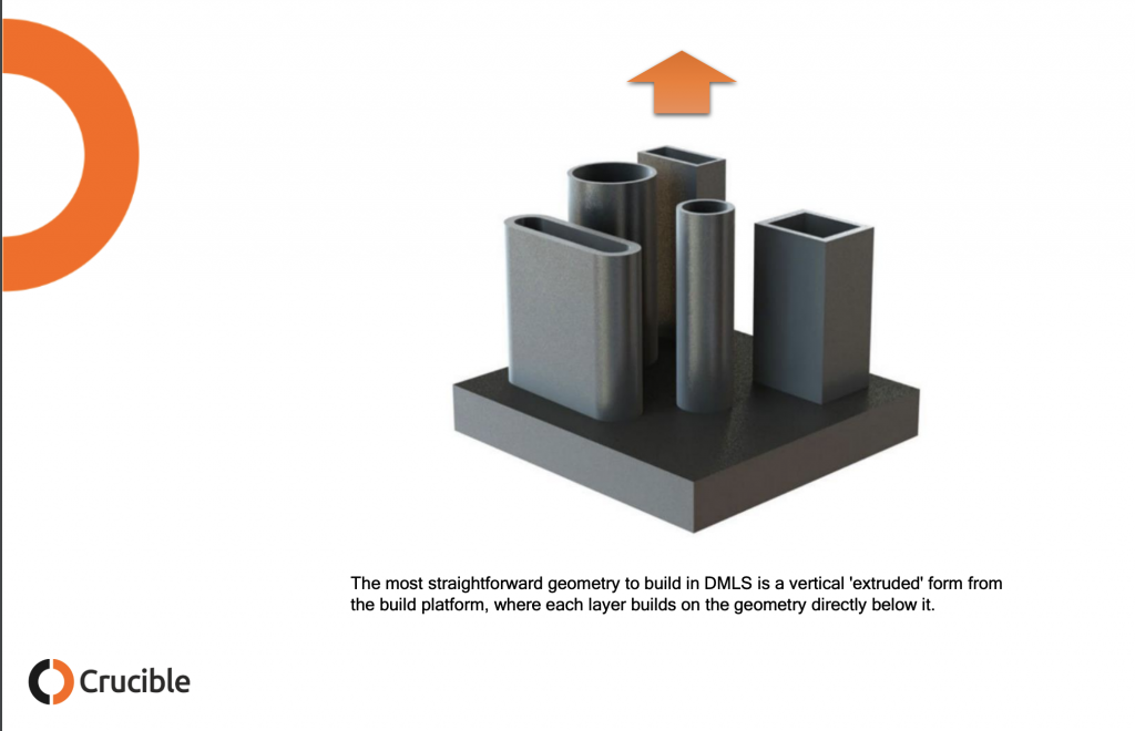
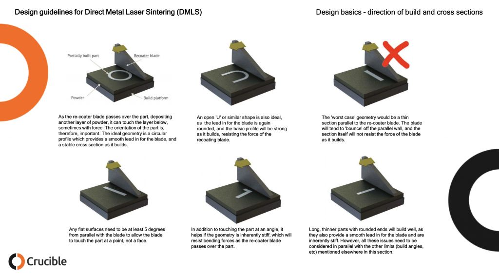
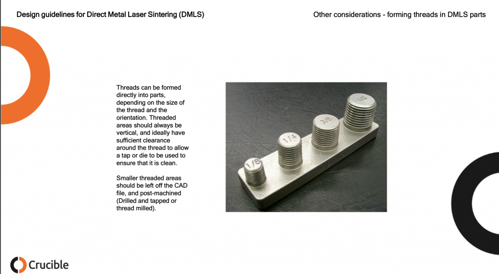
Below we can see how DMLS works. A layer of metal powder around 40 micron in diameter and round but not too round is deposited on a build platform and spread out by a recoater. This may be a roller or a knife blade type of recoater. The laser fuses the powder that will make up your part leaving the other loose powder behind. To keep your part from ripping itself apart due to thermal stress supports are needed which will be removed later.
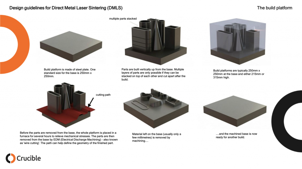
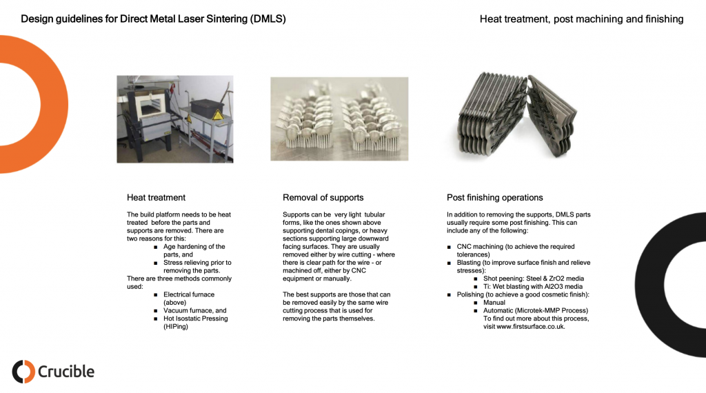
While the build plates below seem very full and indeed parts can be stacked efficiently often single parts are built at a time and parts are not stacked. This has to do with the fact that much of the industry is not yet optimized for production and worry that layer skips or recoater bumps and other errors will disrupt a week long build four days in. Note the high amount of manual labor required here. Every one of the bottom column steps will require a person lifting a few kilos at least to a new station or machine. Not shown here is the manual removal of loose powder. In addition to EDM CNC or tumbling (sometimes for a week or more) may be used as well. Depending on the needed Ra and finish of the part many steps will be required including quality control steps such as CT scanning the part to make sure that there are no internal tears or holes.
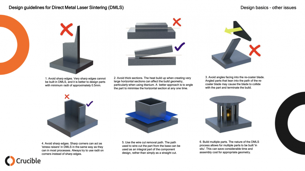
Parts built in such a way as to make it easy for the recoater to hit them with any force and its best to mitigate part strength in such a way that when that does happen your build doesn’t fail.
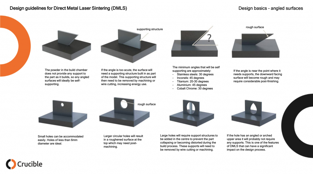
Overhanging surfaces in DMLS can be very rough indeed this may require a lot of post-processing. Occluded holes could trap material inside or require supports that can not be removed while large holes could cause parts to tear themselves asunder.
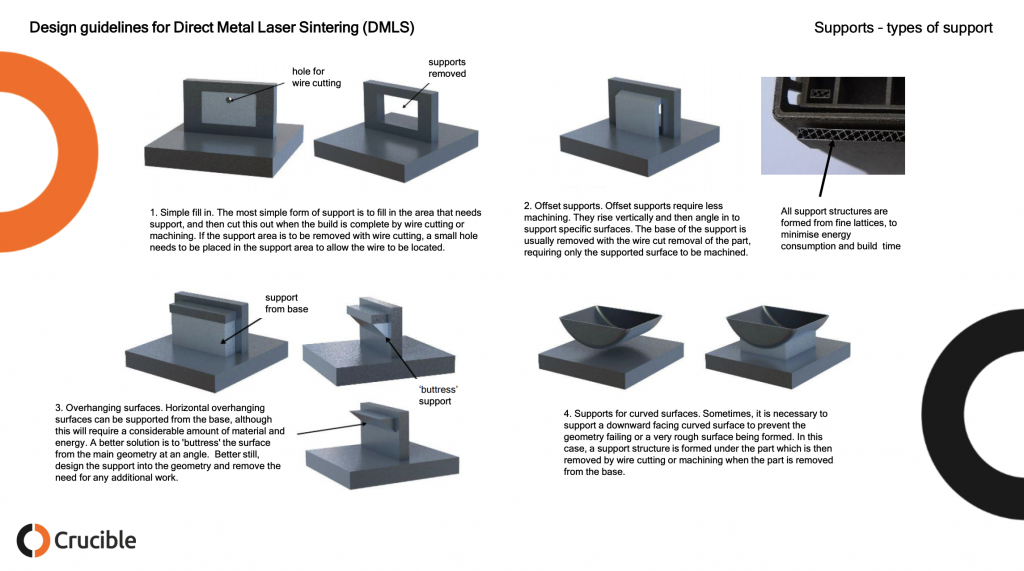
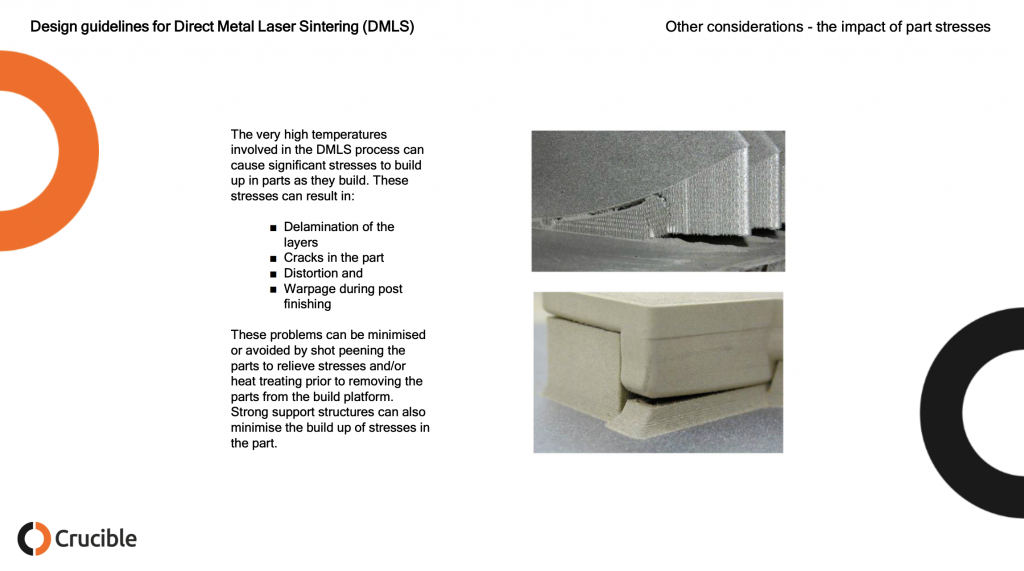
Another thing to consider below is, can the final part withstand the removal of the suports? 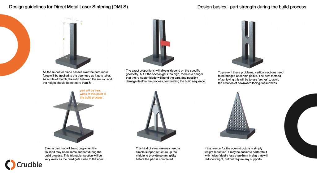
Designing supports that are easy to remove saves a lot of labor. Often a staff member with a flex or circular saw will be cutting away supports. Making sure that this person could do this without damaging the part reduces time and the need to rebuild a part.
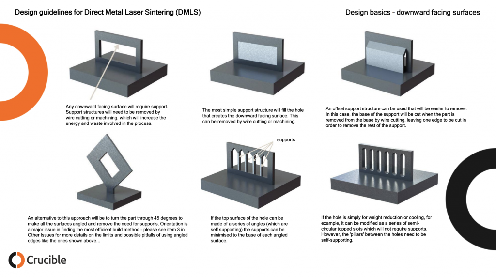
Below are some simple support strategies for DMLS. Often a person with decades of experience can do this in their head. While there are some tools that build supports, support strategies for parts still require a lot of experience and thought. Often it will take days for a build and post processing to complete. If you then after four days find out your part has failed then you have to do another iteration. When making completely new geometries several part failures are common. If you have a type of geometry understood (acetabular cups, teeth) then you can print millions of them in many variations.
Subscribe to Our Email Newsletter
Stay up-to-date on all the latest news from the 3D printing industry and receive information and offers from third party vendors.
Print Services
Upload your 3D Models and get them printed quickly and efficiently.


You May Also Like
PanOptimization Gets Attaboy from AFRL for PanX Software
Published in the International Journal of Advanced Manufacturing Technology, a paper titled “Part scale prediction of residual stress through thermomechanical modeling of additively manufactured Ti-6Al-4V” seems to point to the...
UCLA 3D Prints Zinc-Ion Battery With Seven Times More Energy
Just days after researchers at the California Institute of Technology unveiled a 3D printed design for lithium-ion batteries, another university team has announced a different battery breakthrough using additive manufacturing...
3D Printing News Briefs, July 1, 2026: Prosthetics, Drug Delivery, & More
We’re focused on healthcare and research in today’s 3D Printing News Briefs, including 3D printed prosthetics, patient-specific implants, drug delivery, and more. Read on for all the details! Students from...
New Study Shows Electronics Could Be Manufactured Directly in Space
A team of researchers from Auburn University and NASA Marshall Space Flight Center has successfully demonstrated a new additive manufacturing (AM) process that could allow astronauts to manufacture electronic components...