US Army Characterized Continuous 3D Printed Carbon Fiber-Reinforced Thermoplastic Composite Parts


Geometry of Tensile Specimens.
A trio of researchers with the US Army Tank-Automotive Research Development, and Engineering Center (TARDEC) in Michigan recently published a study, titled “Characterization of Continuous Fiber-Reinforced Composite Materials Manufactured Via Fused Filament Fabrication,” that worked to characterize continuous carbon fiber-reinforced thermoplastic composite parts that were 3D printed on a Mark Two 3D printer.
The abstract reads, “The current work has focused on characterizing the tensile performance of continuous fiber reinforced specimens manufactured via Continuous Filament Fabrication (CFF). The specimens were tested in multiple orientations with and without continuous carbon fiber reinforcement. When comparing 0⁰ carbon fiber reinforced specimens to specimens without continuous reinforcement, the average yield strength, tensile strength, and elastic modulus increased by factors of 20X, 15X, and 240X, respectively. When comparing the results for specimens with 90⁰ oriented continuous reinforcement to the 0⁰ specimens, there was a 60% drop in yield strength, 62% drop in tensile strength, and 52% drop in elastic modulus. These results indicated that mechanical performance is reduced significantly when load is applied perpendicular to the fiber orientations. The adhesion between adjacent layers was tested by printed specimens standing vertically on the print bed. These specimens had the lowest strength of all specimens. The authors recommend follow on testing using rectangular specimens with bonded tabs per ASTM D3039-17 to reduced issues with fiber alignment that were encountered with the dog bone specimens.”
As most 3D printed parts are built from the bottom up, it’s not unusual for out-of-plane material properties to be weaker than in-plane ones. When in-plane printing occurs of continuous fibers, the completed parts can have increased stiffness and in-plane strength, but researchers don’t have a clear idea as to how continuous fiber reinforcements affect an as-manufactured part’s mechanical anisotropy.
“In order for design engineers to utilize continuous fiber-reinforced AM parts in structural applications, they will require the mechanical properties of these materials in three dimensions,” the researchers explained.
The researchers used the nylon-based thermoplastic Onyx by Markforged in their study, along with continuous carbon fiber tow coated with a binder material, and 3D printed several test specimens in order to gain a better understanding of how much of an influence the continuous carbon fiber reinforcement would be:
• Group 1: Onyx (in plane, Nylon/Carbon plastic): ID# 1-1, 1-2, 1-3
• Group 2: 0⁰ fibers (in-plane, aligned carbon fibers):: ID# 2-1, 2-2, 2-3
• Group 3: 90⁰ fibers (in-plane, perpendicular to carbon fibers): ID# 3-1, 3-2, 3-3
• Group 4: z direction (out-of plane, perpendicular to carbon fibers): ID# 4-1, 4-2, 4-3
To make analysis easier, the team only tested specimens with unidirectional fiber orientations. The pure Onyx specimens in the first group were 1.8 mm thick and used as a baseline, while the 0° specimens from Group 2 featured two 0.125 mm layers of Onyx on the roof and floor, along with two Onyx layers on the side walls; the rest was filled with carbon fiber that were “oriented longitudinally in the direction of pull for a tensile test.”
“Additional specimens 3-1, 3-2, and 3-3 were printed with fibers oriented perpendicular to the tensile pull direction. These specimens had the same thickness of Onyx on the roof, floor, and walls as the previous set of specimens,” the researchers explained. “It is noteworthy that for these specimens, since fibers were oriented perpendicular to the direction of tensile pull, the print head must turn corners within the gauge section, and therefore, the fiber orientation within the gauge section was not perfectly unidirectional.”

Schematic of specimens on print bed to show specimen placement and fiber orientation (where relevant).
The Group 4 specimens were 3D printed vertically, and were tested for adhesion evaluation between fiber-reinforced layers. Then, the researchers conducted Thermogravimetric Analysis (TGA) and Fourier Transform Infrared (FTIR) Analysis on the Onyx specimens in order to gain a better understanding of the material’s thermal characteristics; tensile testing was also conducted until total specimen failure.
“When comparing 0⁰ carbon fiber reinforced specimens to pure onyx specimens, the mechanical properties increased by orders of magnitude,” the researchers explained. “For example, the average yield strength, tensile strength, and elastic modulus increased by factors of 20X, 15X, and 240X, respectively. When comparing mechanical performance of the fiber-reinforced specimens to the Onyx material, the significant improvement in mechanical performance is consistent with traditional laminated composites, where unidirectional specimens have strength and stiffness orders of magnitude higher than a homogenous epoxy matrix material. When comparing the results for the 90⁰ specimens to the 0⁰ specimens, there was a 60% drop in yield strength, 62% drop in tensile strength, and 52% drop in elastic modulus. These results indicated that mechanical performance is reduced significantly when load is applied perpendicular to the fiber orientations. However, the relative drop in mechanical performance was not as significant as what is observed for many traditional unidirectional composites tested at 90⁰ orientation. The adhesion between adjacent layers was tested by printed specimens standing vertically on the print bed. These specimens had the lowest strength of all specimens.”
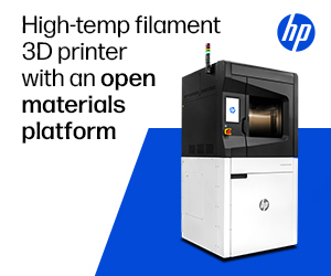
Detailed views of fracture surface of specimen 1-1, showing fiber breakage, fiber pullout, and matrix cracking.
The researchers determined that the materials used in this study have a high degree of mechanical anisotropy, and that others need to consider the 3D anisotropic mechanical properties when they are used in structural applications.
In addition, the team also determined that the traditional dog bone-shaped tensile bars they used for the study were not the best choice for specimens manufactured using CFF, mainly because of “the unique fiber placement process and local variations in fiber angle around the curved radii,” and recommend that other researchers use rectangular specimens with bonded tabs, per the ASTM D3039-17 Standard Test Method for Tensile Properties of Polymer Matrix Composite Materials.
Co-authors of the paper are Robert J. Hart, PhD, Evan G. Patton, and Oleg Sapunkov.
Discuss this research and other 3D printing topics at 3DPrintBoard.com or share your thoughts below.
Subscribe to Our Email Newsletter
Stay up-to-date on all the latest news from the 3D printing industry and receive information and offers from third party vendors.
Print Services
Upload your 3D Models and get them printed quickly and efficiently.


You May Also Like
Australia’s AMCRC Funds Titanium 3D Printing R&D
In terms of the global economy’s presently existing state, there is no realistic path to economic resilience that doesn’t start with critical minerals security. This is a problem for pretty...
3DPOD 305: Automating AM with Grenzebach’s Oliver Elbert
Oliver Elbert‘s over ten years in additive manufacturing have been spent automating LPBF. For large, high-volume, or critical parts, Grenzebach has provided custom automation solutions. Depowdering, powder handling, sieving, heat...
AMPulse Asia: Chinese IPOs, Defense Deals, and Dental 3D Printing Lead APAC Roundup
The second half of June brought a wave of additive manufacturing activity across China, Japan, South Korea, India, and Australia. From Chinese IPOs and funding rounds to defense, aerospace, construction,...
Austal, Curtin University and AMCRC Work on R&D Together
Australia’s Additive Manufacturing Cooperative Research Centre (AMCRC) works with 70 industry partners to deliver collaborative R&D projects. They also work on workforce development and technology transfer. It’s kind of analogous...