

Get It Right the First Time: Perform a Stack-Up Analysis & More on Your 3D Printed Parts

 3D printing can be addictive from every level, whether you are working in the home or office. Once you move past making the initial keychains and phone cases, and humbling yourself with the prerequisite flubs and blobs of melted filament, those more complex, multi-part designs begin to beckon and allow you to make prototypes as well as even low-volume batches of products.
As you move into more advanced 3D printing you may be surprised to find that you have become involved in the study of material sciences, strength testing, and some complex measuring as well. Navigating through an industry and marketplace ripe with tempting software, hardware, and materials, there may not always be a guide to tell you how to make sure your specific print comes out correctly, but one thing is for sure—you don’t want to go to all the trouble of getting your design just right, printing for 18 hours just to have an issue—or worse, send it off to the manufacturer with incorrect dimensions and a surprise waiting for you later.
For those using 3D printing in engineering, and often for very serious work projects, having complex models fit together correctly before they go to production is imperative for saving time and money—not to mention eliminating stress and worry later in the game.
 Tolerance testing is always a part of the process in quality manufacturing and production, and now Fictiv translates that to the 3D printing arena for us in a recent blog, ‘How to Conduct a Tolerance Analysis for 3D Printed Parts.’ A hardware development platform that includes a 3D printing service, Fictiv, headquartered in San Francisco, presented this topic recently for those engaged in fabricating more engineering-oriented commercial products. They also offer access to a free Excel tolerance analysis calculator download.
If you work in or are interested in the area of mechanical engineering and design, then you are probably well familiar with how important it is to perform a tolerance analysis or ‘stack up analysis.’ This is generally an exercise which occurs just before components are sent out to a manufacturer for production.
“This is done to ensure when you order parts, they are manufactured to dimensions that guarantee the components within an assembly fit together,” states Sean Thomas, author of the blog, and a mechanical engineer with over ten years of experience in the defense and energy industries.
Thomas focuses on several things you may eventually need to know how to do:
- Conduct a positional tolerance analysis
- Conduct a linear tolerance analysis
- Employ professional tips and ‘tricks’
In positional analysis, the first thing to consider is tolerance stack and interference. In a 3D printed product if you have a mismatch where holes are supposed to be lined up appropriately for something like connecting a lid and base (even with perfect alignment for screw holes in the center), obviously there is going to be a problem—and that means back to the drawing board—along with a sigh of relief that you didn’t send that part and design off to the manufacturer without testing first.
For the purposes of describing the various parts of analysis, the Fictiv team used a specific prototype, with the end goal of having the measurements correct. Imagine the lid and base assembly, comprising a series of of ¼ – 20 socket head cap screws, serving to fasten the gray lid to the green base. Obviously, meticulous measuring and placement are key, and there should be consideration for a range for error.
“The fasteners have a maximum outer diameter of 0.250”, but they will also have to pass through holes in the lid and thread into the tapped holes in the base,” states Thomas. “For a 0.250” diameter fastener to pass through a plain hole, the diameter of the hole would have to be just larger than 0.251. However, when these components are manufactured, the holes will not be in the exact same locations as the model due to machine capabilities.”
In testing for proper positional analysis, the example of measurements with bolt holes is used. The team used an excel calculator meant just for this exercise.
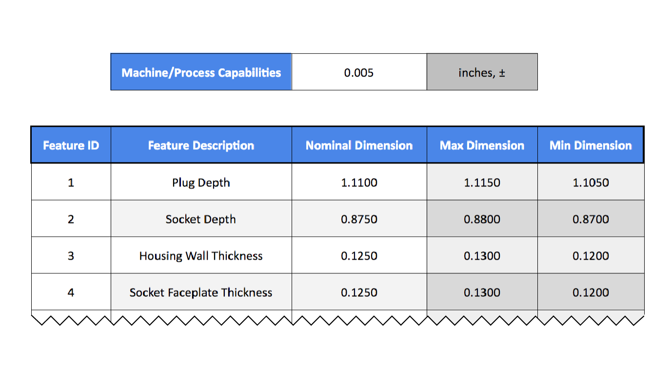
“In the spreadsheet, there are separate tabs for positional and linear tolerance studies and the lighter columns on the left require user input and the darker two columns on the right are the calculated spreadsheet output,” said Thomas.
Four pretty simple steps are explained by Fictiv, as you use their spreadsheet to complete your analysis.
First, Define the Machine or Process Capabilities – Both Stratasys and Fictiv use a tolerance specification of ±.005” for an FDM machine.
Second, Define Interfacing Components and Associated Dimensions – Figure out what the interfacing features are; for example, here they are the screw holes and screws, required to see that all areas line up and allow for proper installation together.

Third, Calculate the Necessary Clearance – Using the formula provided above by Fictiv, you are able to figure sizes according to machine performance specifications.
“This formula is based on the fact that if the axes of the holes are displaced relative to each other at the maximums of each tolerance, the displacement will be equal to the hypotenuse of a right triangle with sides equal to .010”. The image below illustrates a ±.005” tolerance zone, and the associated hypotenuse. Note that the sides are .010” which is simply twice the .005” we are using for the machine tolerances,” states Thomas.
Doubling the hypotenuse is necessary to add to the clearance from a diametral standpoint due to displacement between hole axes. Then, once again, you must add in tolerance because the hole ‘may come in undersized.’ If you use the formula below, it’s obvious that the lid’s clearance holes should be sized as: 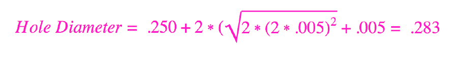
Keep in mind that rather than doing calculations yourself, it’s much easier to employ the Excel calculator—and the team at Fictiv is obviously a big fan of using it too.
Fourth, Adjust the CAD Model Accordingly – To reflect all of the aforementioned dimensions you’ll want to detail those, and the tolerances for the hole sizes and spacing. It’s important to remember that your parts will never come in as they were dimensioned within the model.
Looking at the original lid and base model, the holes are spaced at 2.150” and 1.500” from the center planes of the part, while the through holes in the lid will be modeled to a diameter of 0.283”. As Thomas points out, with a machine producing parts that are at the tolerance zone extremes, part dimensions could vary enough that you have to change the CAD models. That is a worst-case scenario, but certainly not impossible.
“It’s obvious that even with the most drastic offsets in part dimensions, the parts still fit together. Statistically speaking, it’s very unlikely that all of these dimensions will come in at these extremes, but this method will ensure the parts fit together the first time, every time, with no modification,” states Thomas.
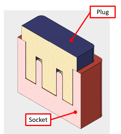 Once you’ve completed that more lengthy process, you’ll want to work on practicing a linear tolerance analysis, using the same basic steps as before. The idea for this example is to look at a linear stack and to examine multiple interfaces and their spacing, relative to each other. For the part, the Fictiv team used a rectangular plug to be inserted into a socket of the same shape. The obvious goal here is to achieve an interlocking fit.
“We want the larger shoulder of the plug to contact the top of the socket to ensure the plug doesn’t bottom out,” says Thomas, who puts the correct dimensions into the spreadsheet for finding out the dimensional extremes.
“If the part is manufactured to the nominal dimensions, we can see there will be .015” of clearance between the end of the plug and the bottom of the socket cavity. However, this clearance gap can be reduced as low as .005” if the part is produced to the tolerance extremes of the machine as detailed in the image below.”
In using the spreadsheet, you can calculate the clearances after you subtract max plug depth dimension (0.990) from the min socket depth dimension (0.995).
The issue, according to Thomas, is when interfacing components (like faceplates) are added, and tolerances begin to stack up. That’s when you begin increasing the odds for tolerance stacking to become unfavorable, but with the ‘same nominal clearance’ as in the first case.
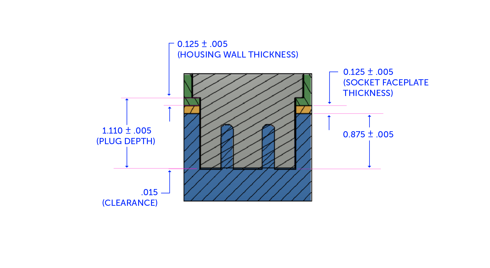 If you refer to the calculations provided in the blog, you’ll see that Thomas has to add an additional clearance at .010” to accommodate the stacking of the housing and faceplate. Just keep in mind that as you add more components between parts during the design process, challenges will increase as well.
Very important too are tips and tricks offered by the Fictiv team.
- If you are okay with a bit of gambling—as well as cleanup—you can reduce the clearance instead of opening tolerances to make sure of a perfect fit.
“Remember, tolerance stack ups are a game of statistics, and the further you deviate from a guaranteed fit, the greater your chances of ‘busting’ are,” states Thomas.
- The more interfaces you have, the greater the opportunity for issues. Remember that it is okay to cut down on the volume of interfaces that must work together.
- When seeking precision, keep in mind that it’s much better to limit the size of the parts and to be very careful regarding manufacturing processes.
“Many of the higher end processes (like Polyjet) will produce more accurate parts, and nearly all machines will hold tighter tolerances as your parts get smaller as long as it doesn’t exceed the feature size capability of the machine.”
It’s also important to keep in mind that for the purpose of learning about the process here, you are seeing worst case tolerance analysis examples which would be indicative of parts being ordered in low volume scenarios, often just needed as ‘drop-in replacements’ for existing assemblies. If you are considering larger quantities, or have to deal with extremely tight tolerances, studies are recommended to examine whether or not parts will fit together ‘over wide ranges of tolerance stacks.’ It’s also recommended to use the Monte Carlo simulation for smaller quantities when trying to figure out the worst case scenario, and the probability of parts fitting. Was this information helpful, and might you try one of these tests? Discuss in the 3D Printing & Tolerance Testing forum over at 3DPB.com.
Subscribe to Our Email Newsletter
Stay up-to-date on all the latest news from the 3D printing industry and receive information and offers from third party vendors.
Print Services
Upload your 3D Models and get them printed quickly and efficiently.


You May Also Like
3D Printing News Briefs, April 25, 2026: Competition Winners, AI Platform, X2D Printer, & More
In this weekend’s 3D Printing News Briefs, AMUG announced the winners of its Technical Competition, and Authentise launched AI platform Whisper at RAPID. Bambu Lab wasn’t at RAPID, but launched...
RAPID 2026: 6K Additive’s Domestic Metal Powders & Consolidation Plan
6K Additive (ASX: 6KA), a U.S. supplier and manufacturer of metal powders for additive manufacturing (AM), has been very busy lately. I caught up with CEO Frank Roberts and Chief...
3D Printing News Briefs, April 22, 2026: DINOs, Post-Processing, AM for Aerostructures, & More
We’ll start with event news in today’s 3D Printing News Briefs, as AMUG presented its DINO Award to six members at this year’s conference, and Axtra3D celebrated its five-year anniversary...
Medical, Electronics, & Semiconductors: Detailed 3D Prints at RAPID 2026 with Boston Micro Fabrication & Lithoz
They say that good things come in small packages, and that’s certainly the case when it comes to Boston Micro Fabrication (BMF). A leader in micro-precision additive manufacturing, the company...