
3D Scanner Review: The Artec Eva and Artec Studio 15 Software

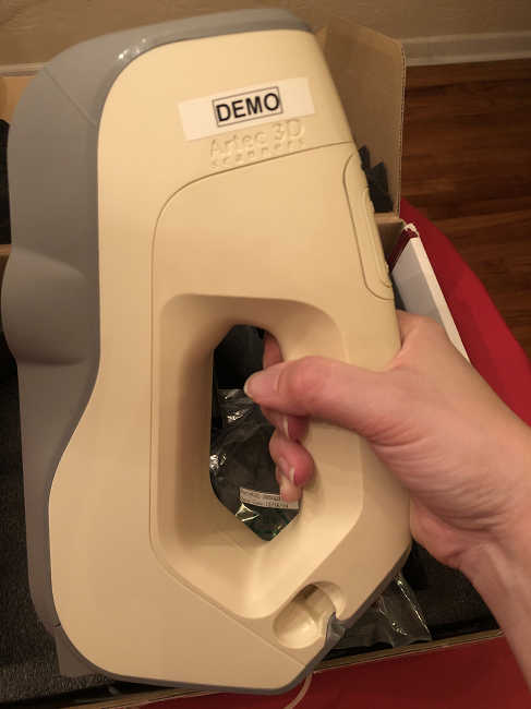
One of the first stories I ever wrote for 3DPrint.com was about a custom sleep mask for a patient with Graves’ disease, which often causes the eye to protrude and makes it extremely difficult to get a good night’s sleep. A handheld Artec 3D scanner, specifically the Artec Eva, was used to create a textured 3D image of the patient’s face in order to make a mask that would perfectly fit her so it could block out the light and allow her eyelids to close while asleep. We listed the Eva scanner as a “trusted 3D scanner that is versatile and can be used for many applications” in our 2020 3D scanner buying guide, and with its proven portability and capacity for scanning difficult reflective surfaces, imagine my excitement when I had the opportunity to review an Artec Eva demo unit for myself.

Please enjoy this picture of Millie inspecting the box
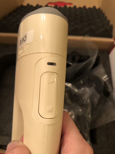
So, here are the important specs about this structured light 3D scanner, which weighs less than two pounds and was once named the best 3D scanner under $50,000 by iReviews:
- up to 0.1 mm accuracy
- up to 0.2 mm 3D resolution
- full-color scanning
- target-free tracking
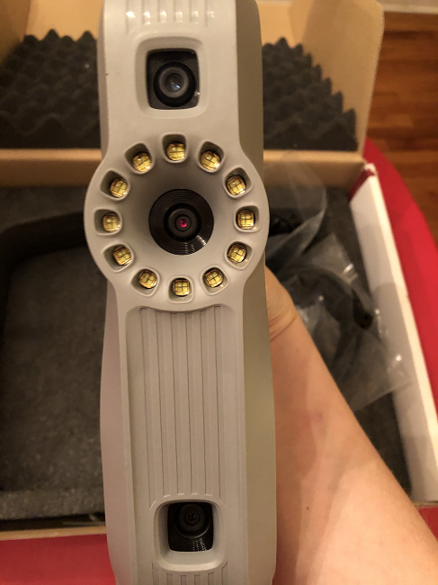
- 12 white LED array 2D light source
- flashbulb 3D light source
- 3D reconstruction rate of 16 frames per second (FPS)
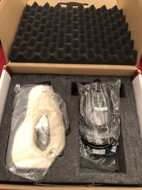
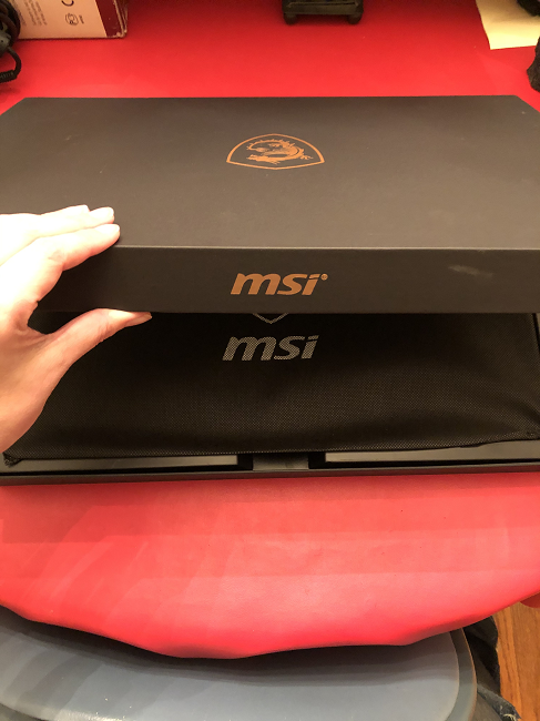
The Artec Eva came well-packaged with the various cords; as it operates by USB streaming through an external computer, it has to remain plugged in to the computer during scanning. Along with the scanner, Artec 3D sent me the fanciest laptop I’ve ever seen: an MSI system with light-up keys and a wireless mouse to go with it.
The laptop was pre-loaded with Artec Studio 15 software, which was just released this summer and has a variety of useful features, such as an HD mode for high-resolution scans, excellent geometry tracking algorithms, and Smart Base Removal. When the software opens, a menu directs you to several online tutorial videos, including one about the Artec Studio interface and another about basic scan processing. So, before I did anything else, I watched a few of the tutorials, and then got to work setting everything up.
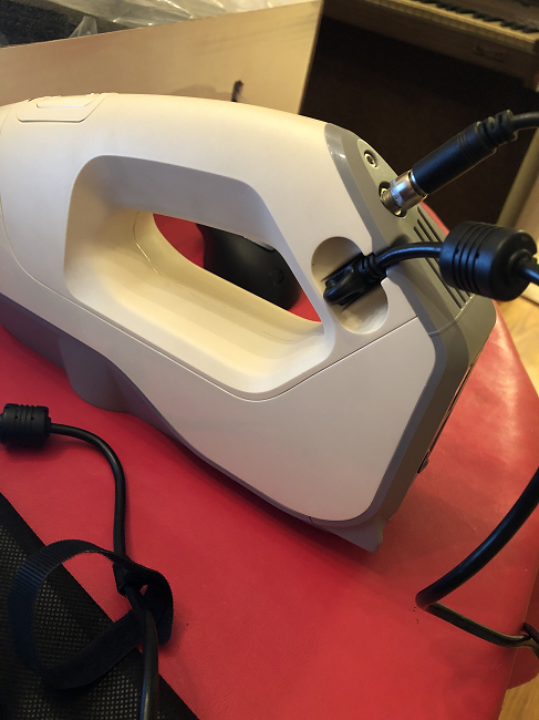
This is probably just the nature of most handheld scanners, but it was difficult at times to keep all of the cords out of the way during scanning. I had the laptop plugged into the wall, the scanner plugged into the wall, and the scanner was also plugged into the laptop, so movement was a little limited. But since the Artec Eva is good for quick, detailed scans of medium-sized objects, it wasn’t like I needed to travel very far.
I quickly figured out how to work the scanner, as it’s quite user-friendly and a green light turns on once it’s all ready to go. I thought I’d start small for my first scanning project, and spied the decorative ceramic teacup I have on an end table in my dining room.
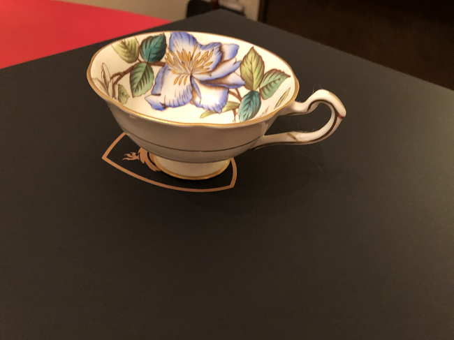
The teacup on the laptop box
I put the small, shiny object on top of the black laptop box for what I figured would be good contrast (you can laugh if you’re skilled at scanning and recognize all of my mistakes), aimed the Eva at the teacup, selected “Preview” in the software, and pushed the button to start scanning.
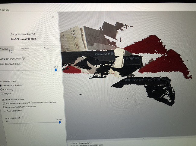
The disastrous scans of the teacup on the laptop box
Suffice it to say, my first scan did not go well. But it gave me a good chance to continue investigating the various software features, such as checking out all of the individual frames I captured during the scan.
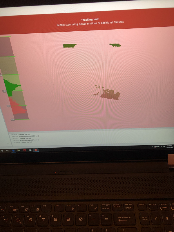
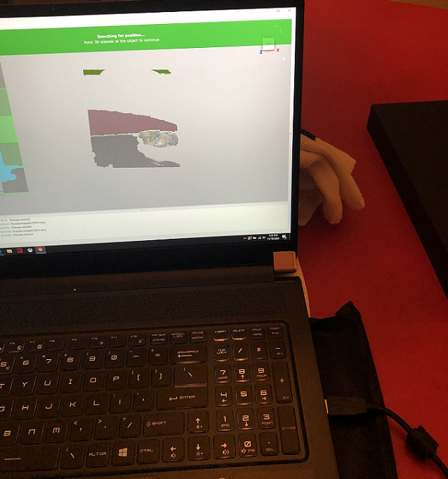
Distance color map
The Studio 15 software was really great at explaining what the problem was, and how to fix it. One of the first things I learned was that I didn’t need to look at the object I was scanning, but instead at the computer screen. This way, I could make sure I wasn’t moving the scanner too fast or too slow and had it the right distance away from the scan object. I learned that, for best results, I should keep my scan movements in the middle three boxes on the left of the screen, known as the distance color map, which you can see in the image above. The distance from the scanner to the object is displayed by color in the frames, and just like traffic lights, green means go (or good in this case), and red means stop (not so good).
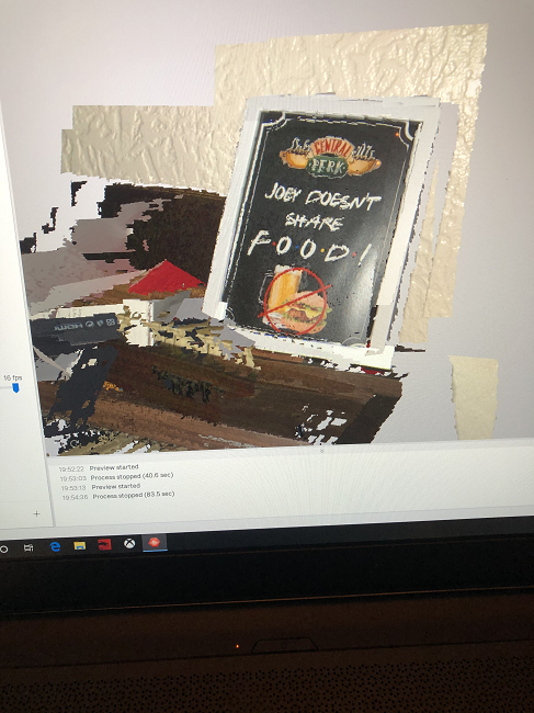
I tried one more time that night, with something completely different: our mini organ with a framed photo of a favorite Friends quote on top. It was really more of an accident instead of a plan, as I’d captured some of it in the background during one of my attempts to scan the teacup and realized it was showing up pretty well. It definitely wasn’t the best result, but I felt satisfied that I could at least tell what the scan was in the software, which had not been the case with the teacup, as you can clearly see above.

My breakthrough came after the first of two training sessions with Olesya Kopteva, Artec 3D’s Training and 3D Scanning Team Leader. She provided and went over two very helpful handouts with me, the first of which covered the basics. You need good lighting, preferably from a fixture and not natural sunlight streaming in through a window; you need to ensure that the scan object is immobile and determine how difficult it will be to scan ahead of time; and while you’re scanning different angles of the object, you need to keep moving your wrist consistently at a steady pace, similar to spray-painting. Additionally, if you have other objects near the scan object, like your 3D scanner box, you’ll likely capture them too, so either move them out of the way or prepare for a lot of editing.
Kopteva explained what constitutes good geometry, as compared to bad geometry, when it comes to scanning an object. To successfully track an item, it needs to be a little larger than something like, say, a teacup. It should have rich geometry, as opposed to the flat geometry you’d see on a teacup. Corners and edges are better than round geometry…again, like a teacup has. Do you see where I’m going here?
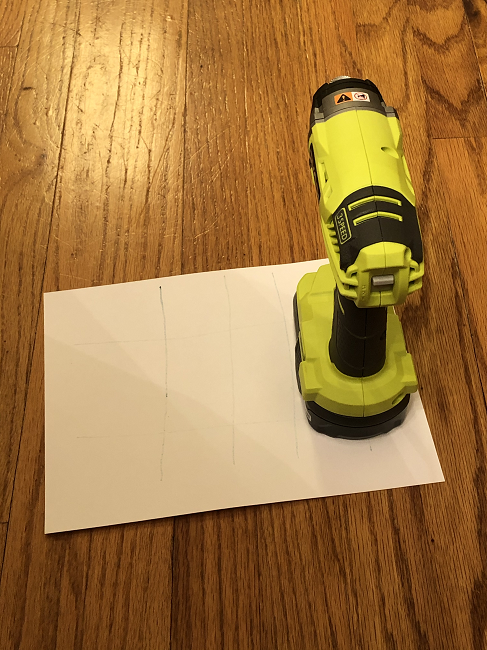
In terms of texture, scanning works better with high contrast, multiple colors, visible color borders, and unique patterns. I also learned that shiny, reflective surfaces—like my teacup—are much more difficult to scan, and that contrast doesn’t just mean putting a flat black surface under the scan object, like I had done with my first ill-fated scanning attempt, or using my red tablecloth. Instead, Kopteva said I should draw some dark lines on a white piece of paper and use that for the base.
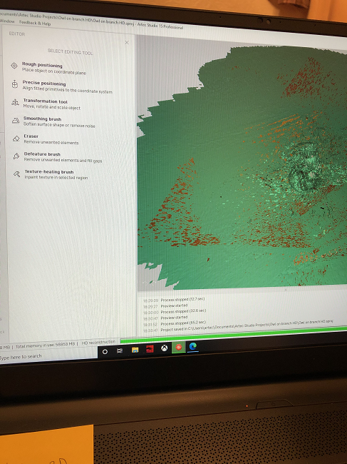
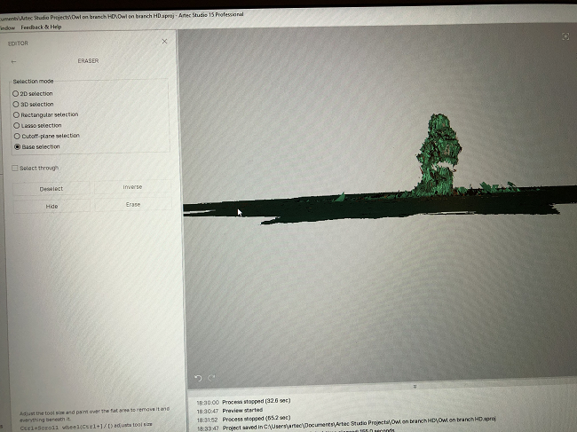
Once I got finished laughing at how I had broken every single rule of good scanning on my first try, Kopteva discussed the scan processing workflow with me. I was familiar with the steps from watching the tutorial, but she was able to go into greater depth about everything. The first step to perform is to edit the scan, which entails erasing the background, base, or other unwanted elements, like the scanner and computer cords, from the scan. There are several eraser options, including 2D selection, which reminded me of drawing fat lines in Microsoft Paint; rectangular selection, in which you draw rectangles around larger areas you need to erase; and base selection, which erases all the selected areas below the scan object.
She showed me how to align two scans, but also explained that if I captured enough data in one go, I would only need one scan, and, therefore, wouldn’t need to mess with the tricky alignment tool. I learned how to check my scan in Max Error mode, which again uses color to show any defects in the data, and how to complete Global Registration for the scan, which basically converts all the 3D frames into a single coordinate system.
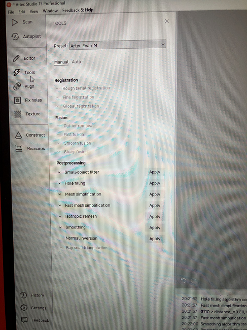
In the Fusion section of the tool workflow, you can start with Outlier Removal, an optional step that removes all the tiny bits of “noise” around the scan that you didn’t catch during editing, and then you choose how you want to fuse all your frames together into one model: Fast, Smooth, or Sharp. As Kopteva explained, Sharp Fusion is the most commonly used, due to its smart hole filling and sharpening of fine geometry. The quickest is Fast Fusion, but it doesn’t fill any holes and leaves most of the noise. Smooth Fusion takes longer because it smooths the geometry and removes the noise. The Small Object Filter can delete the noise from any unwanted objects from the fusion, but you need to remember to click the “all except largest” option if there’s only object, and it’s the biggest.
The Mesh Simplification step reduces the number of polygons your model has, as by default the mesh has more polygons than necessary. By taking away polygons, the model requires less space and is easier to work with, which is helpful. Fast mesh simplification is the default option, and the fewer polygons you end up with, the less of the model’s geometry will be maintained.
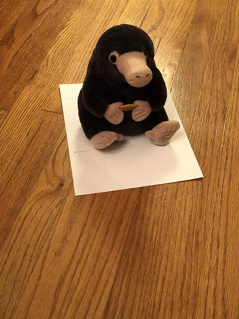
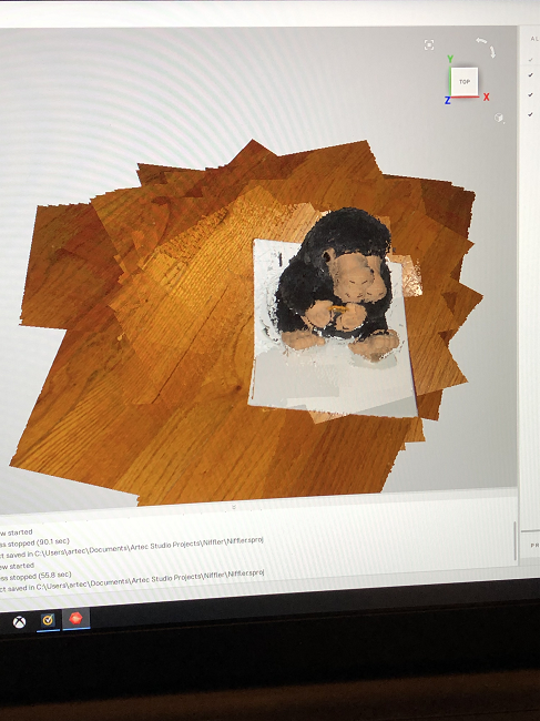
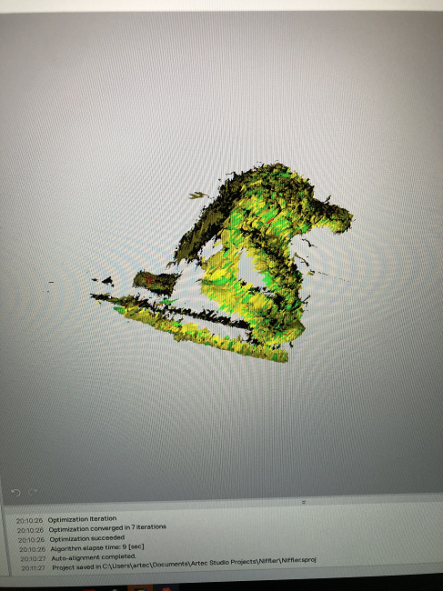
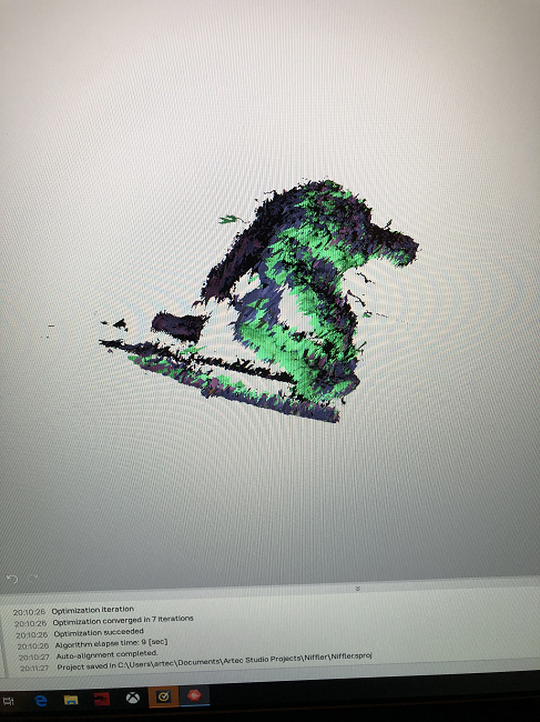
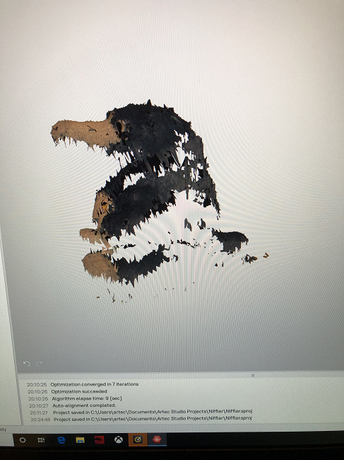
Once I got off of the Zoom training session with Kopteva, I was ready to dive back in, and decided to try scanning my stuffed Niffler from the Harry Potter Fantastic Beasts and Where to Find Them movies, as it had a fluffier texture. The whole process was a lot easier the second time around. However, I wondered what I was doing wrong that I was getting so many gaps in the scan data, like you can see in my scans of the Niffler below. I was glad that at least you could tell what it was, which is more than I can say for my first attempt.
I got a little big for my britches next and thought it was time to go big or go home, and attempted to scan our Wet/Dry Vacuum, as it was easily accessible while my husband was working on redoing our bathroom at the time. It was definitely bigger than a teacup, and had pretty rich geometry.


Again, I could tell what the object was in the software, but as Kopteva told me later in our second training session, it’s not good to stop and start and take multiple scans of a complicated object like this from various angles. This is why a long, single scan, capturing all the angles, is better if you can manage it. The reflective, black hose of the vacuum didn’t do me any favors either.
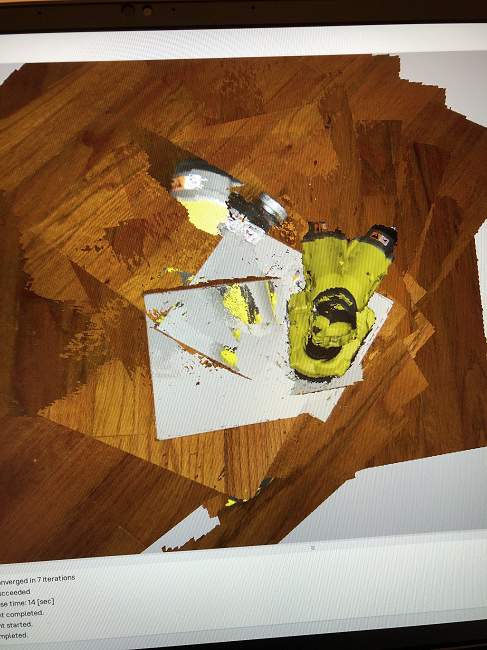
In an effort to scan objects that could potentially be good applications for the technology, as opposed to stuffed animals, I tried to scan a drill next, which seemed fine but went off the rails when I tried to align two scans, and I finally resolved that I would stick to long, single scans.
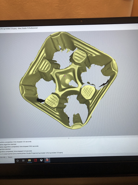
My first real success came when I decided to try scanning the cupholder I was about to throw away from a morning coffee run. I noticed that it was textured, with pretty interesting geometry, and decided to give it a go.
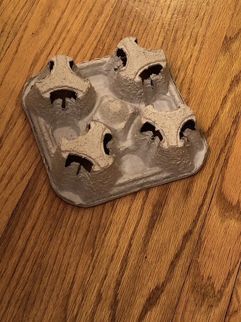
I was immensely proud of my cup holder scans, and in our second training session, Kopteva introduced me to the Artec Eva’s HD mode, which is actually a setting that you choose in the software, and not a button that you push on the scanner itself.
HD mode can increase the resolution of your scan up to two times, as well as remove noise, improve the curvature of your edges, and enable better reconstruction of areas that are hard to reach and surfaces that are tricky to scan. This last feature is why Kopteva thought my cup holder would be a good test subject for an HD scan. HD is better to use when your scan object has a lot of noise and is tough to scan, with thin parts, while SD mode is mainly for simple shapes, less time-consuming projects, and more powerful computers.
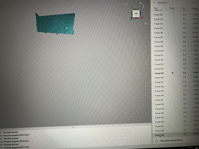
The processing definitely takes longer when you’re in HD mode, which you need to remember to select as an option both before you start scanning and before you start editing. Kopteva’s handout suggested that, for a good HD scan, you need to capture 2000-3000 frames, which you can easily keep track of on the right side of your screen. Because of the vast amount of processing required, you need to unload your scans before you start working them, which just basically saves them in a folder. Once you exit the scan screen and go into your editing tools, you can reload the scans.
-
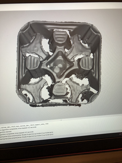
- SD mode
-
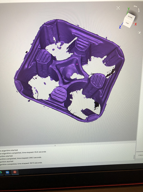
- HD mode
You can definitely tell the difference between an SD scan and an HD one, as illustrated in the pictures above of my cup holder.
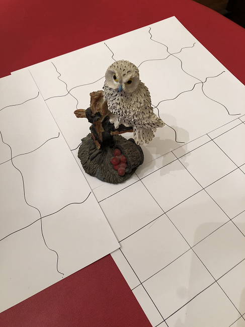
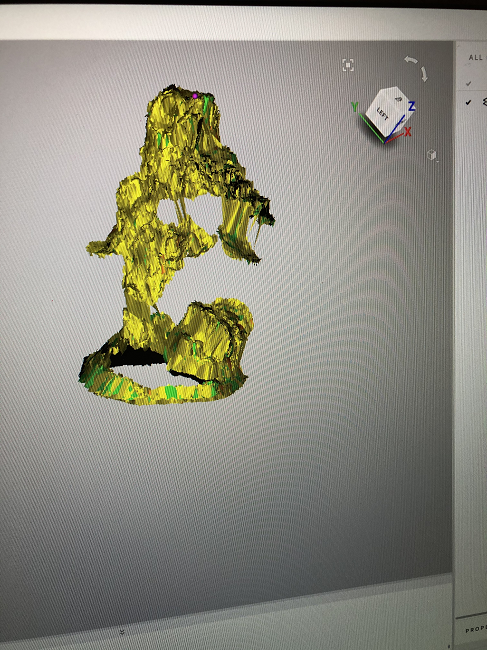
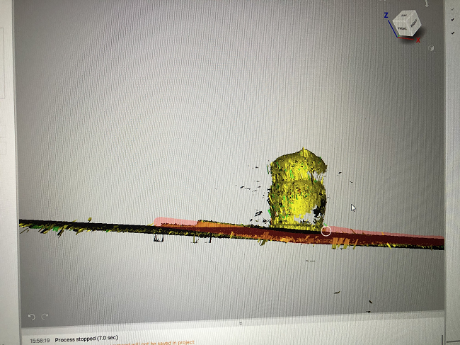
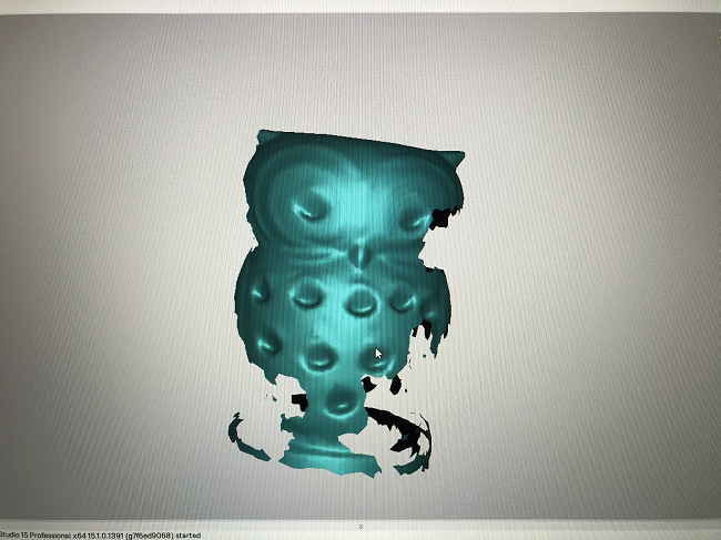
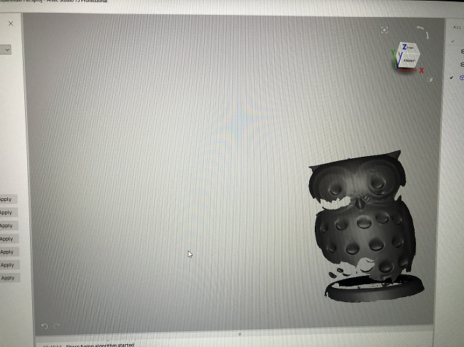
Kopteva also told me that I should try scanning some small to medium-sized figurines with interesting geometry from around my house, going back and forth from SD and HD mode. She also told me to keep an eye on the color map during scanning to ensure I was capturing enough of my objects so I wouldn’t have such big gaps. I eventually settled on a pretty good pace for scanning, and just kept going over the objects multiple times to make sure I had enough data.
You can check out the results below from my owl figurine scans:

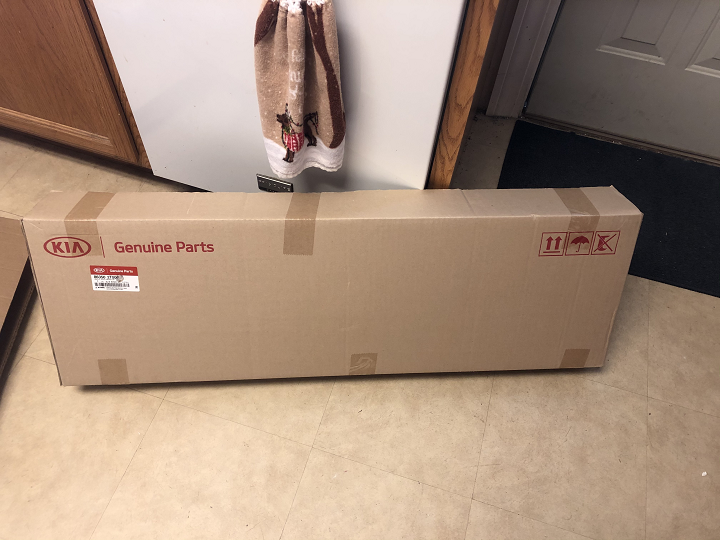
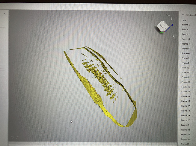
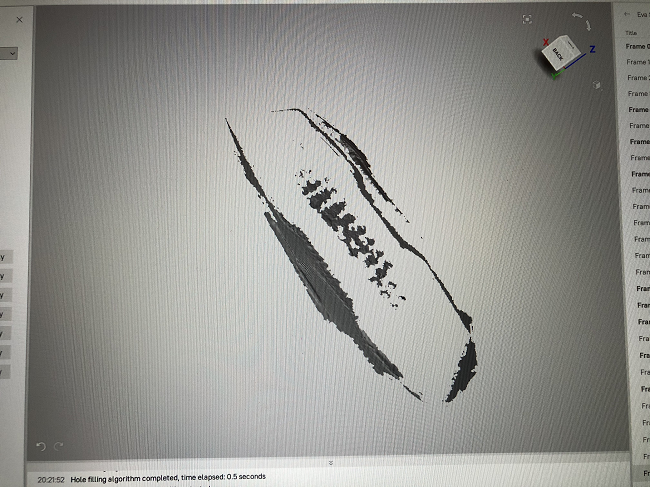
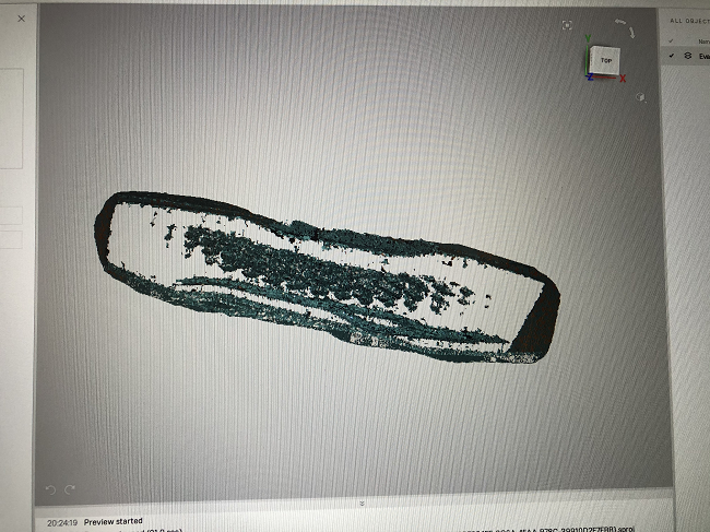
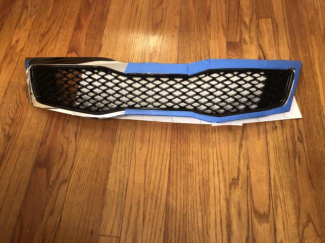
I received an email from Artec right as I was about to start packing everything up to send back, asking if I’d like them to send me some scan objects that might be used in real-world applications, and I quickly agreed. I don’t know exactly what I was expecting, but it definitely wasn’t a plastic car grille for a Kia:
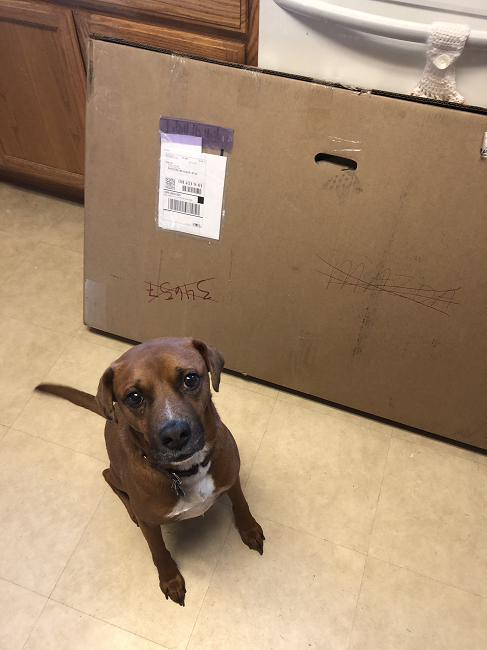
Dash was very excited about this box.

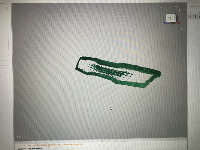
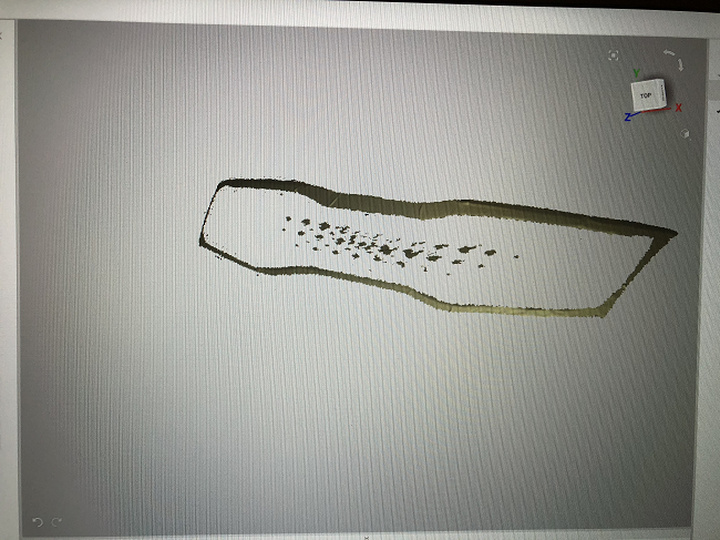
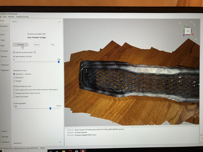
I realized quickly that this would a be pretty tough scan, due to the shiny, reflective, and black materials, but I was excited to try.
Obviously, it did not go well at first.
Basically, dark surfaces absorb the light from the scanner, while reflective ones scatter the light and bounce it out to different directions; both cause the scanner to be unable to really “see” the object in its field of view. I remembered Kopteva mentioning that you could sprinkle or spray a couple of different materials onto the item to help combat the reflectivity, so I did a little research and found some scanning tips on the Artec website.
One suggestion was to use a scanning spray or other coating on the object, while another was to adjust the angle and distance of your scan, in order to find which combination will allow the surface to be scanned best.
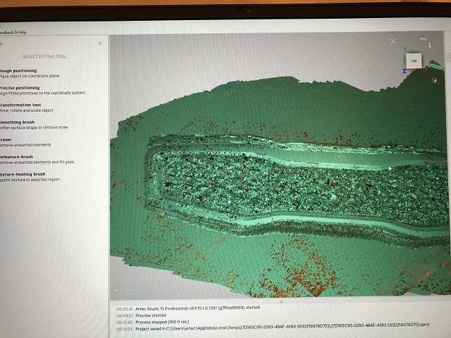
Making these adjustments definitely helped, but only a little. I didn’t have a scanning spray, so I did some more internet digging to see if there were any objects currently in my household that might help. I found that if you don’t need the color for your scan, you could cover shiny parts of the object with painters tape, which we had in abundance.
Again, this helped, but only for the shiny edges. I would need something else to enable 3D scanning of the many black crisscross shapes in the middle of the part.

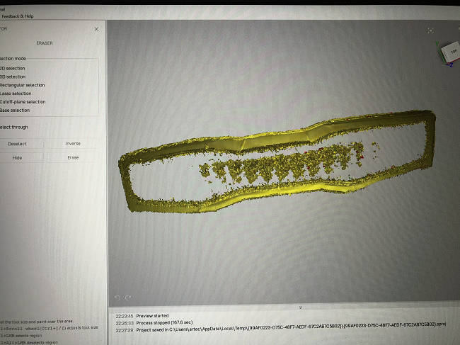
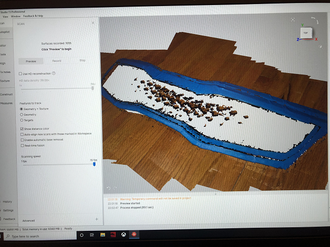
Finally, I found a list of some common and not-so-common household alternatives to 3D scanning sprays on Artec’s website. You could use aerosol spray paint, talcum powder, dry shampoo, water-based paint, deodorant sprays, and Gold Bond foot/body spray, which is what I opted to use. The website stated that it was easy to apply, and would create “an even and uniform antiglare layer on the object.” Luckily, they had it at our neighborhood pharmacy, so I spread some newspapers out on the kitchen floor, placed the car grille on top, and started spraying.
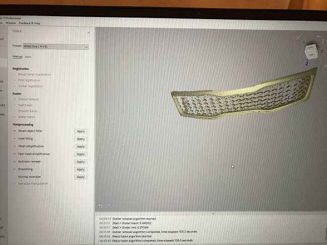
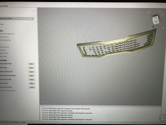
The difference it made was remarkable:
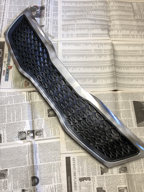
The Gold Bond spray was able to get into all of the grille’s nooks and crannies, which allowed me to capture data from the entire object, instead of just the edges.
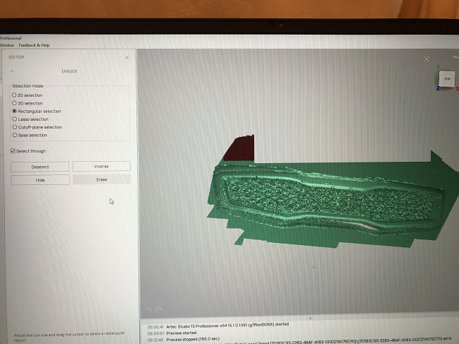
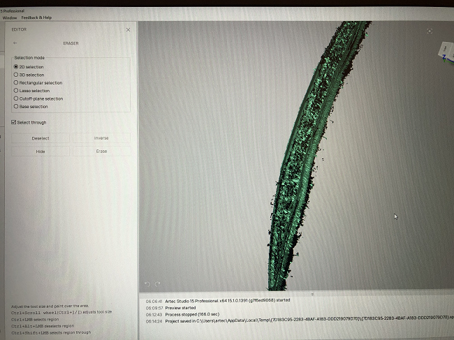
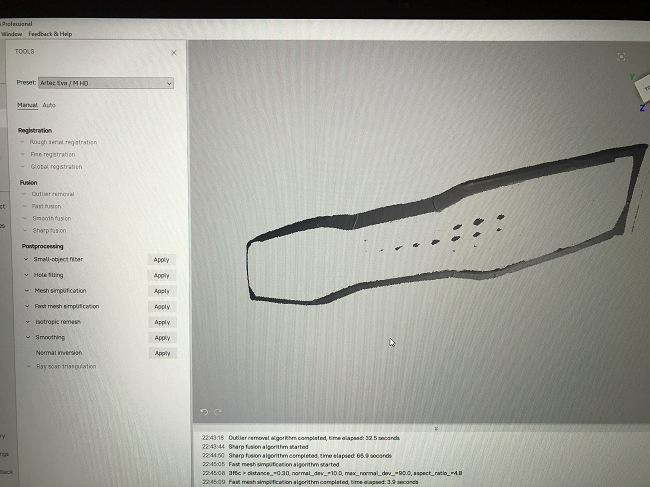
A lot of editing work was involved for this one, but once you get the hang of all the tools, the process is pretty easy, and I actually found the erasing step to be almost therapeutic.
My final 3D car grille model wasn’t perfect, but I still felt it was pretty successful compared to where I had started.

In terms of ease of use, I was able to set up and start using the Artec Eva 3D scanner pretty quickly, but using it well, and figuring out the software, was something else entirely. I definitely wouldn’t call the workflow difficult. But Artec 3D makes sure that users have access to many handy training tools, like video tutorials and tips, and I found my Zoom training sessions to be extremely helpful. I almost think the amount of support you have access to when learning how to use a new device matters more than how quickly you can pick it up and start using it perfectly, because it shows that the company wants you to succeed and is giving you the proper tools to do so.
(Photos courtesy of Sarah Saunders)
Subscribe to Our Email Newsletter
Stay up-to-date on all the latest news from the 3D printing industry and receive information and offers from third party vendors.
Print Services
Upload your 3D Models and get them printed quickly and efficiently.


You May Also Like
AMPulse Asia: Creality IPO Headlines APAC 3D Printing Market Roundup
Asia’s additive manufacturing sector spent the back half of May moving capital and capacity, not just demos. Chinese desktop and consumer printer makers pushed onto public markets, metal powder producers...
Blue Origin’s New Glenn Explosion Comes During Major Manufacturing Push
Blue Origin‘s orbital New Glenn rocket exploded during a hot-fire test at Launch Complex 36 in Cape Canaveral on May 29, setting back the company’s launch ambitions at a time...
Aibuild Says New FETS Simulation Tool Is 10,000x Faster for AM
Aibuild has launched FETS for Additive Manufacturing, a Finite Element Thermomechanical Simulation tool that lets you simulate stress, distortion, thermal effects, and thermomechanical effects. The solution has been optimized for...
AI CAD Tools for 3D Printing: An Overview
There is a bevy of AI-to-CAD tools coming out. Some are finding users; some are raising millions in funding. Many new ones are coming out all the time, so we...