Maker Upcycles IKEA Tables for 3D Printer Enclosure, Solves Temp & Calibration Concerns


IKEA, alternately being lauded for the joys of modern design and affordability and mocked for ridiculous assembly complications and spindliness, is often a source of inspiration for the creative community, famous for its appreciation of the ubiquitous Scandinavian designs and their attractive price tags.
As Instructables member Sean Veck, of Southampton, sat one day evaluating his 3D printer that was giving him a few problems due to calibration and temperature issues, it occurred to him that some leftover parts from an IKEA table might pose as a great enclosure.
“I had a few ‘Lack’ tables from IKEA laying about,” Veck said, “and noticed that when stacked atop each other, the printer fit almost exactly inside, this gave me the idea to create an enclosure for the printer, how hard could it be?”
Hoping to alleviate overheating, calibrating, and delamination issues, Veck added some extra parts to the list, and came up with the following inventory needed for assembling his 3D printer enclosure: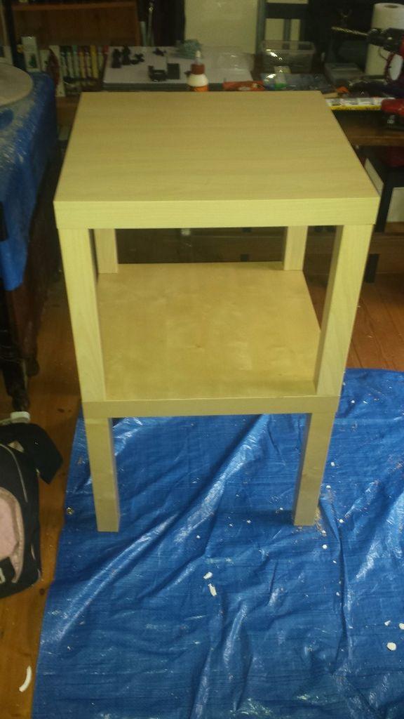
- Transparent windows on each side
- Removable door, rather than hinged, for ease of assembly
- Extractor fan to rapidly cool the environment
- Voltage and temperature readings
- Lighting
- Mounts for the controller board, Pi, and power supply on the back
Parts
- 2 IKEA Lack Tables
- 4x Arcrylic Sheet 400 x 450 x 5 mm
- 12v LED strip lighting reel
- 120mm computer fan
- 12v digital thermometer display
- 3-30v digital voltmeter display
- 2x round rocker switches w/ LED
- 8x neodymium magnet 10 x 3 mm
- 16x corner braces
Consumables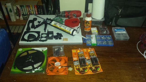
- Wood glue
- Epoxy adhesive
- Silicone sealant
- Wood screws
- Rubber grommets
- Various M3 and M4 bolts & nuts
- Heatshrink tube, various sizes
- 12v wires
- Hot glue
- 4x wooden pins
Printed Parts
- 120mm Fan Aperture
- 2x Handle
- 4x magnet surround
- ~10x zip tie bracket
- Pi bracket
He recommends turning one of the tables upside down to drill off-center holes as guides in the legs for using a screw to attach the top to the leg.
Use wood glue to coat the pins and insert them snugly into the holes, with glue applied at the other end, and to the top of the table also. With the tables on top of each other, gently press them together and then let the glue dry overnight. The two together should aid in the design and eliminate complications and irritation from vibration.
 Designate which pieces will function as which walls (left, right, etc.) and then mark holes for drilling. Once engaged in doing so, use caution in avoiding catching of the acrylic and screws, so that there isn’t any malfunction or breakage. (Note: a laser cutter is strongly recommended.)
Once you’ve attached all the sides, and the wood glue has dried, it is time to assemble the enclosure in entirety, mounting the power rack.
“I intend for the enclosure to be fairly self-contained, only needing one power lead and ethernet cable,” says Veck. “Be careful when drilling the pilot holes, as the Lack is very cheaply manufactured and the walls are extremely thin.”
You may also need to cut and sand the acrylic sheets after mounting the corner braces, as he did. After you finish drilling all the appropriate holes according to Veck’s more detailed instruction, it’s time for a test fit–and also a great opportunity for adding reinforcement with hot glue around the braces. After that you can attach corner magnets on the doors using epoxy.
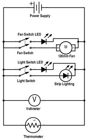
Follow Veck’s diagram to connect components and power supply, which is connected to the back of the rear acrylic sheet. Attach the Pi cradle, fix everything to the back and reconnect wires from the 3D printer to the enclosure.
“If you have an LCD, it is a better idea to run this cable on top of the enclosure and fix it there,” states Veck. “Peel the film off of and attach the right panel once you have the wiring done.”
 Making sure this enclosure has no possible way of coming apart, ever, Veck recommends tightening all the bolts for the frame and then sealing the edges with silicone.
“When applying silicone sealant, you’re compressing the silicone slightly, so after you release the trigger, silicone will keep coming out of the nozzle,” says Veck. “Bear this in mind less you make a mess!”
Once you’ve connected all the appropriate wires and run a test, you should have a stable voltage reading if all is well. After that, you just need to wait for that sealant to dry and then you’re ready to test the enclosure.
Without connecting the power supply to your printer, attach the two wires from your enclosure wiring and run a test. Make sure that all of the components work and the voltage reading is stable.
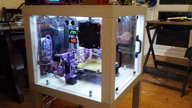
Once the silicone has dried, you are ready to test your enclosure.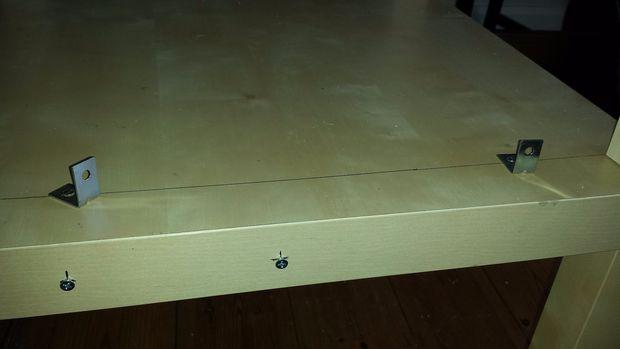
“Slice up something small and hit print,” recommends Veck. “You should notice that the bed heats up a lot quicker–it cut the time mine took by about 20 minutes, and the temperature in the enclosure should rise slowly. Mine topped out at around 40c.”
If all goes according the plan, you should find that your room won’t heat up like an oven on Thanksgiving day, and calibration and delamination issues should be lessened. Veck had not done a substantial print with the enclosure attached yet, but plans to release future updates with progress.
Is this a design you are interested in? Discuss in the 3D Printer Enclosure forum thread over at 3DPB.com.
Subscribe to Our Email Newsletter
Stay up-to-date on all the latest news from the 3D printing industry and receive information and offers from third party vendors.
Print Services
Upload your 3D Models and get them printed quickly and efficiently.


You May Also Like
Beyond Thermoplastics: Why JuggerBot Is Betting on Hybrid AM
For years, thermoplastics have been the workhorse of additive manufacturing (AM). They are pretty easy to process, available, and compatible with many of today’s industrial 3D printers. From prototypes to...
RIC Robotics Collaborates with K4k Construction on 3D Printed ADU in Sacramento
In 2024, RIC Robotics, the additive construction (AC) firm based in Denver, completed the build of an accessory dwelling unit (ADU) in Walnut, California, which was apparently an industry first....
Printing Money Episode 40: 3DP/AM Deal Analysis and More with Matthias Schmidt-Lehr, AMPOWER
Welcome to Printing Money Episode 40. Matthias Schmidt-Lehr (AMPOWER, Executive Partner) joins Danny for this episode and we are very thankful to have him back. In Episode 40, Danny and...
Additive Manufacturing at a Crossroads
Additive manufacturing is at a crossroads. Simultaneously, we find ourselves between certain very different modalities, applications, and industries. Rather than being able to explore them all, companies will now have...