
3D Printing Metal End-use Part Applications

This article describes the ideal use-cases for each process & comparison with other solutions to help you identify opportunities using 3D Hubs in your organization for metal 3d printing service.
Definition: End-use part is any good that is either sold as a product or placed in service within a company’s internal operations.
There are 6 processes to consider:
- FDM / FFF (plastics)
- SLA / DLP (plastics)
- SLS / MJF (plastics)
- SLM / DMLS (metals)
- Metal FFF (metals)
- Binder Jetting (metals)
In part 1 we talked about plastic parts, in part 2 we discuss only metals.
4. SLM/DMLS
Selective Laser Melting (SLM) and Direct Metal Laser Sintering (DMLS) are metal powder bed fusion 3D Hubs printing processes that are most commonly used today as they are especially suitable for high-end applications since they offer advanced material properties and superb design freedom.
While both utilize high laser power to bond together metal powder particles to form a part– layer-by-layer, SLM will achieve a full melt, while — due to the very high temperatures — DMLS will cause the metal particles to fuse together at a molecular level.
The majority of metal alloys are compatible with the DMLS method, wherein SLM, only certain (pure) metal materials may be used.
Still, the differences between these two 3D Hubs printing technologies are so slim; they can be treated as the same for designing purposes.
In this section, we will take a closer look at the technical characteristics, manufacturing process, and the limitations and benefits of these two, very similar techniques.
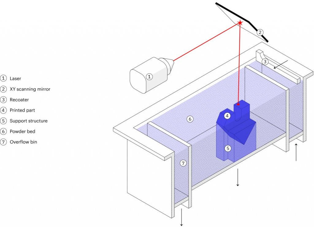
How it works: SLM/DMLS 3D Hubs printing process basic steps:
- First, the build chamber is filled with inert gas then heated to the optimum print temperature.
- A thin layer (typically 50 μm) of metal powder is spread over the build platform.
- Next, the laser scans the cross-section of the part, selectively bonding the metal particles.
- Thus, the build platform moves down a layer when the entire area is scanned, and the process repeats until the build is complete.
- After the printing process is complete, the build must first cool down before the loose powder is extracted.
This step is only the beginning of the SLM/DMLS 3D printing manufacturing process. Once the print is complete, several compulsory and/or optional post-processing steps are also required before the parts will be ready for use.
Compulsory post-processing steps include
- Stress relief: Before continuing with any other operation, the internal stresses that develop during printing, due to the very high processing temperatures, need to be relieved through a thermal cycle.
- Removal of the parts: In SLM/DMLS the parts are welded onto the build platform and EDM wire cutting or a band saw are used.
- Removal of the support: To mitigate the distortion and warping that occurs during printing, support in SLM/DMLS is required. Support is CNC machined or removed manually.
Additional post-processing steps are often required to meet engineering specifications that may include:
- CNC machining: When tolerances are tighter than the standard ± 0.1 mm that’s required, machining is employed as a finishing step. Only the slight material is removed this way.
- Heat treatments: Hot Isostatic Pressing (HIP) or heat treatments can be used to improve the material properties of the part.
- Smoothing/Polishing: Certain application requires a smoother surface than the standard RA 10 μm of as-printed SLM/DMLS. CNC machining and Vibro, chemical, or manual polishing are available solutions.
How it works: Laser source bonds metal powder particles
Strengths:
- Geometric freedom
- High accuracy & fine details
- High-performance materials
Materials:
- Stainless Steel
- Aluminum
- Titanium
- Superalloys
Use case #1 – Optimized brackets
DMLS / SLM is used to create lightweight parts through advanced CAD processes, such as topology optimization. They are of particular interest in the automotive and aerospace industries.
Use case #2 – Internal geometries
A far more common use of DMLS / SLM is the creation of parts with internal channels. These find applications in the manufacturing industry (for example injection molding tooling with internal channels for cooling) or for heat exchangers.
Pro tip: Make sure that no support structures are needed to manufacture the internal channels, as they will be impossible to remove.
5. Metal FFF: What is metal extrusion?
Metal Extrusion is a low-cost metal 3D printing process alternative that is most suitable for prototyping purposes or for one-off custom parts.
It is a variation of the classic FDM method for plastics. In 2018, the first Metal Extrusion 3D printers were released also known as an Atomic Diffusion Additive Manufacturing (ADAM) and Bound Metal Deposition (BMD).
A part is built layer-by-layer, like FDM, by extruding material through a nozzle, but the material is not plastic, unlike FDM but is a metal powder held together with a polymer binder. The result of the printing step is a “green” part that needs to be sintered and de-bonded to become fully metal.
Here, we examine the characteristics and key limitations and benefits of this additive process to help you understand how you can use it more effectively.
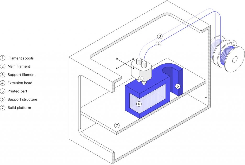
How does metal extrusion work?
Metal Extrusion consists of a three-stage process involving a printing stage, a de-binding stage, and a sintering stage.
The Printing Stage…
- Raw material in a rod or filament form, which basically consists of metal particles that are bound together by wax and/or polymer.
- This filament or rod is extruded through a heated nozzle and then deposited– layer-by-layer to build a designed part based on the CAD model.
- While, if necessary, support structures are built. The interface between the part and the support is printed with ceramic support material that can easily be removed later manually.
When printing is complete, the “green” resulting part must be post-processed using similar steps like Binder Jetting, in order to become metal. The “green” part is washed first for several hours in a solution to remove almost all of the binders. Then it is sintered inside a furnace so that the metal particles are bonded together to form the fully-metal part.
During the sintering process, the dimensions of the parts are reduced by about 20 percent. to compensate for this, the parts are printed larger. Like the Binder Jetting process, the shrinkage isn’t homogenous, meaning that trial and error will be required to get accurate results for particular designs.
How it works: Metal/binder is extruded through a nozzle to print the part, which is then thermally sintered.
Strengths:
- Does not require industrial facilities
- Based on MIM
- Complex metal parts
Materials:
- Stainless steel
- Tool steel
Main use: For internal operations
An alternative to CNC, Sand casting
Quantity: 1-50 parts
Use case #1 – CNC part replacements
Metal Extrusion is excellent for functional CNC prototyping and small productions of metal parts that would otherwise require a 5-axis CNC machining to produce.
6. Metal Binder Jetting
Metal Binder Jetting is increasing in popularity rapidly. What makes it especially suitable for small to medium production runs, is its unique characteristics.
In this section, we will dive deeper within the steps used in the Binder Jetting to learn the basic characteristics of metal parts production.
What is Metal Binder Jetting?
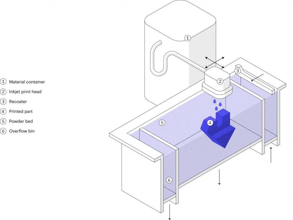
Metal Binder Jetting is a process of building parts by placing a binding agent on a slightly thin layer of powder in through inkjet nozzles. Originally, it was used to develop full-color models and prototypes from sandstone. A variation of the technique is becoming more popular lately, because of its batch production capabilities.
In metal Binder Jetting printing, the printing step is done at room temperature, which means the thermal effects, such as, internal stresses and warping aren’t a problem, like in SLM/ DMLS, and therefore, supports are not needed. To create a fully metal part, an additional post-processing step is required.
How does Metal Binder Jetting work?
Metal Binder Jetting involves two-stages; a printing stage and a post-processing stage.
The printing process works like this…
- A thin layer (typically 50 μm) of metal powder is spread out over the build platform.
- A carriage that has inkjet nozzles will pass over the bed while selectively depositing binding agent droplets of wax and polymer to bond together the metal powder particles.
- When done, the build platform will move down, then the process will repeat until the entire build is complete.
The result of this printing process is a part of the “green” state. To create fully metal parts and remove the binding agent, a post-processing step is necessary.
This post-processing stage requires two variations: Infiltration and Sintering.
How it works: Binder is jetted onto metal powder particles to create the part, which is then thermally sintered
Strengths:
- Great design freedom
- Based on MIM
- Batch production
Materials:
- Stainless steel
- Tool steel
Main use: Low-run metal production
An alternative to Metal Injection Molding, Die casting
Use case – Low-run production
Binder Jetting is the only metal 3D printing technology today that can be used cost-effectively for low-to-medium batch production of metal parts that are smaller than a tennis ball.
Why engineers use 3D Hubs for 3D printing
Instant quoting & DFM feedback
Build and edit your quote online. Review your parts for manufacturability and assess the cost of different materials, processes and lead times for your project in real-time. Explore our 3d printing service for every type of additive manufacturing project.
Readily available capacity
Benefit from our network of 250 manufacturing partners to access instantly available capacity. Our manufacturing partners are both local and overseas.
Quality & reliability
Dedicated 3D Hubs team to ensure your parts consistently meet your quality expectations. We also offer phone, email and chat support for any concerns or questions you may have.
Subscribe to Our Email Newsletter
Stay up-to-date on all the latest news from the 3D printing industry and receive information and offers from third party vendors.
Print Services
Upload your 3D Models and get them printed quickly and efficiently.


You May Also Like
3D Printing Financials: 3D Systems Returns to Growth in Q1 2026
3D Systems (NYSE: DDD) reported one of its strongest quarters in recent years, showing signs that the company may finally be moving past the tough slowdown that has weighed on...
3D People Case Study Details Development of 3D Printed POV Camera Rig
A POV, or Point of View, camera rig, is a wearable support system that helps filmographers capture first-person footage, making the images more immersive. Some good examples of movies shot...
3D Printing News Briefs, May 2, 2026: Soft Robots, Agricultural Waste, & More
In this weekend’s 3D Printing News Briefs, we’ll start off with a multi-laser metal powder bed fusion 3D printer and post-processing news. We’ll end with research into soft robotics and...
Industrial Applications on Display at RAPID 2026: CERATIZIT & 3D Systems
Applications are where it’s at in the additive manufacturing (AM) industry. At the recent RAPID+TCT in Boston, I met with a few companies to learn about some of their very...