Researchers Tim Kuipers, Eugni L. Doubrovski, Jun Wu, and Charlie C.L. Wang have released the findings of a new study in the recently published ‘A framework for adaptive width control of dense contour-parallel toolpaths in fused deposition modeling.’
Adaptive widths are effective for use in FDM 3D printing, but as the authors point out, they can often be challenging to set. In this study, the researchers create a framework for numerous schemes in generating adaptive-width toolpaths. Today, users often employ technology with extrusion occurring along parallel toolpaths following along with the contour of the layer, leaving the authors to focus on these methods—along with discussing solutions for challenges found in narrower geometries.
When features vary from nozzle size, there may be issues with both overfill and underfill as respectively, a buildup of pressure is caused, or a decrease in stiffness that may threaten stability or cause features to be completely overlooked in printing. Such issues are more exaggerated in prints with smaller details; however, these problems may be avoided in using toolpaths with adaptive width.

Illustration of different toolpaths for a shape showcasing a range of shape radii (black). These results can be read as a graph with feature size on the horizontal axis and its corresponding beading along the vertical axis. (a) Toolpaths using uniform offsetting results in large overfill (orange) and underfill (azure). (b) Toolpaths with adaptive width [9] where beads that are wider or narrower than the nozzle size are indicated in red and blue, respectively. (c) Our approach minimizes over- and underfill with less extreme widths
- A path for extrusion that is as continuous as possible, avoiding defects and failure
- Smooth performance—avoiding sharp turns and a longer printing process
- The ability to cover the contour region without underfilling
- No overlap in extrusion paths
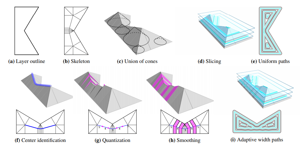
The first row illustrates the generation of uniform paths (e) by interpreting the path as the intersection between horizontal planes and the union of cones (c),
which is an alternative visualization of the skeleton (b). The second row depicts the stages with both 2D and 3D visualizations for generating paths with adaptive width (i). Central elements in the skeleton are first identified (blue in (f)). The heights are then quantized in terms of number of beads (the integer values in (g)), and smoothed (h).
The researchers began by creating a graph for the input polygon—as a skeleton, representative of the medial axis transform (MAT). Noting that the skeleton is meant to be visualized as ‘the union of cones,’ each point is raised to a height equaling the least distance from the point to the boundary of the polygon. Edges and nodes are discovered first, in the center. New nodes are then added, with the union of cones being sliced at regular intervals.
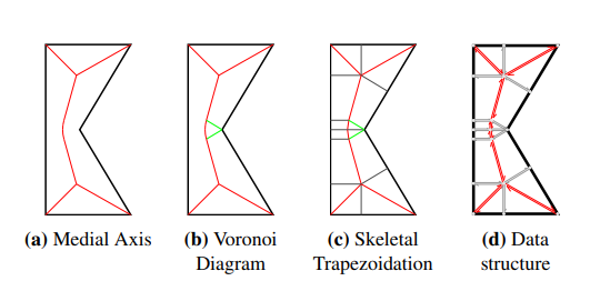
Skeletonization of an outline shape (black). Relation between the medial axis (red), the limited Voronoi Diagram (red and green) and the Skeletal Trapezoidation (red, green and gray): MAT ⊂ Limited VD ⊂ ST. (d) The skeleton is represented using a half-edge data-structure.
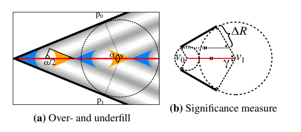
Properties of the significance measure along a skeletal edge (red) generated from two polygon lines (black) using the properties of inscribed circles (gray) and their radii (dashed). (a) The size of overfill (orange) and underfill areas (azure) for the uniform toolpathing technique can be calculated from the bisector angle. (b) The significance measure can be simplified using α = 2γ = 2 cos−1 ∆R/|v1 − v0|.
Toolpaths of 300 sample shapes were generated with the framework created by the authors, using four beading schemes.
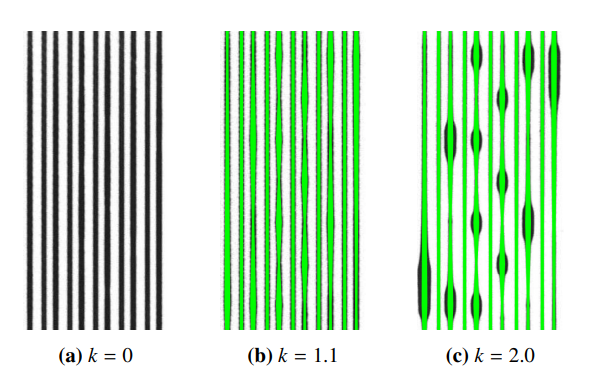
Print results (black) of the varying width test on top of a dense white raft. Target widths in green. (a) Simple flow equalization without back pressure compensation results in nearly constant bead widths. (b) A value of k = 1.1 seems to produce good results
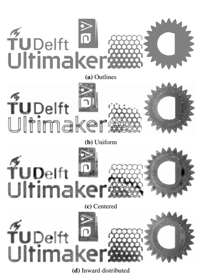
Test shapes printed using the uniform scheme, centered scheme and the inward distributed scheme. The uniform technique produces distinct underfill areas. The centered scheme shows some defects due to inaccurate control of extreme deposition widths. The inward distributed scheme produces the least defects.
The authors evaluated sample structures for:
- Accuracy
- Uniformity
- Print time
- Computational performance
- Comparison of beading schemes
- Limitations
- Applications
Overall, the researchers found their framework to be stable in evaluation, further refined for thin contours and microstructure prototypes.
“Our framework is flexible, demonstrated by the several beading schemes which emulate existing techniques. The computation times of our framework are on par with the state-of-the-art library for performing offsets of non-adaptive bead width,” concluded the researchers.
“Compared to the naive approach of constant width toolpaths our beading scheme is expected to improve the stiffness, dimensional accuracy and visual qualities of the manufactured model. It is expected that as distributed beading schemes are implemented in commercial software packages and bead width variation control become commonplace, the practice of design for additive manufacturing can disregards some of the nozzle size considerations.”
Toolpaths are the topic of ongoing research around the world, from using them to avoid 3D printing collisions to creating different simulations and levels of optimization. What do you think of this news? Let us know your thoughts! Join the discussion of this and other 3D printing topics at 3DPrintBoard.com.
[Source / Images: ‘A framework for adaptive width control of dense contour-parallel toolpaths in fused deposition modeling’]