Researchers D.W. Abbot, D.V.V. Kallon, C. Anghel, and P. Dube delve into complex analysis and testing in the ‘Finite Element Analysis of 3D Printed Model via Compression Tests.’ For this study, the researchers used an FEA tool for simulation and testing of 3D printed parts, with a central focus on experimenting with ‘specific imposed conditions’ on the sample models—employing a strategy that allows for much faster, more affordable assessment of parts.
FEA allows researchers (and ultimately, manufacturers) to prove a variety of different prototypes created through other methods—but now a serious focus is being placed on parts printed in numerous different materials, to include ABS, PLA, and more. Square block samples were chosen for the study due to the potential for better accuracy and distribution of stress along surfaces—with the goal of allowing engineers to finally ‘trust’ FEM in terms of 3D printed objects.

Properties of some 3D printing materials.
Compression testing involved labeling 3D printed samples as either isotropic or anisotropic, with a focus on avoiding anisotropy and inter-layer voids. In examining the samples, the researchers were able to see the internal structures of FDM 3D printed parts, along with evaluating densities. Both experimental and computational tests were performed.
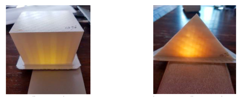
(left) 15% quality prototype in ABS, (right) 85% quality prototype in ABS
“Results obtained using Autodesk Inventor are compared to the experimental test results. The arrow represents the direction in which the load has been applied to that of the axes experiencing the load. The horizontal axes, the original axis that the objects are printed on, representing an axially distributed load from above, against the grain of the layers, the vertical axis represents an axial load that would be experienced from the side of the test specimen, with the grain of the layers.”
FEA is centered around both the materials and techniques used, along with design—and the researchers point out that this could be different depending on the simulation software used. Both porosity and adhesion are both issues too. The researchers continued to note the ‘large discrepancy’ also between both experimental and simulated results, with test pieces exhibiting 50 percent more solidity than the experimental samples.

(left) before applied load, (right) after applied load
On noting that samples ‘behaved poorly’ regarding horizontal/perpendicular loads, the researchers realized the 3D printed block samples were anisotropic. Infill simulated results and experimental results differed greatly too, as the Autodesk design and simulation were viewed as a solid (instead of porous) object; in fact, in some cases, the samples were not similar at all.
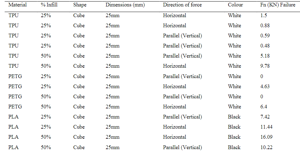
Practical test results
In observing samples (or functional parts), it is critical to evaluate:
- Area of application
- Environment of use
- Operational associated stress at specific axis
“The results obtained from this study on different materials at different applied loads across the two different layering axes showed a large variation in compressive strength,” concluded the researchers. “This establishes that the design of 3D parts strongly depends on the application of the part.”
While 3D printing offers a wide range of benefits, the ability to edit designs and create one iteration after another at will is one of the greatest draws in comparison to more conventional methods of production. Researchers today are engaged in many different types of feasibility studies, ways to introduce new workflow features and learn more about cost analyses.
What do you think of this news? Let us know your thoughts! Join the discussion of this and other 3D printing topics at 3DPrintBoard.com.
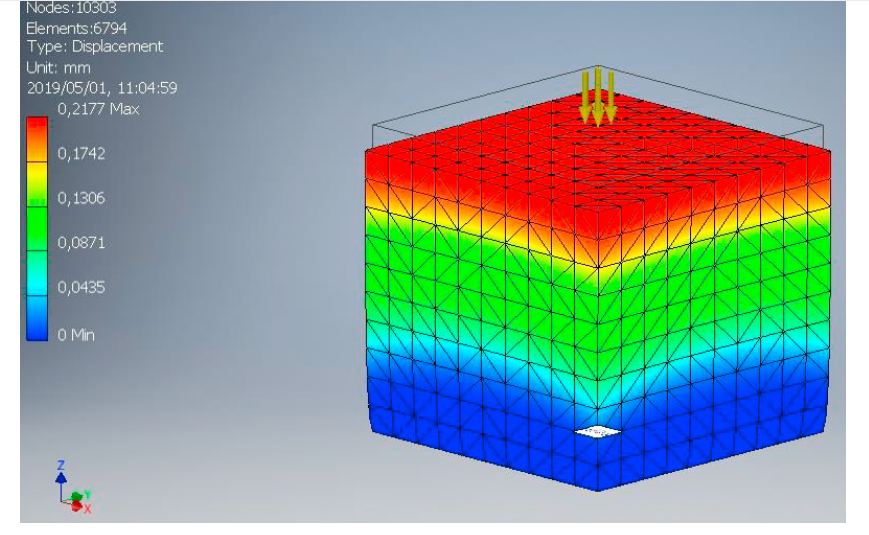
Maximum displacement at 12200N for ABS Plastic using Autodesk Inventor