Anyone with small children will tell you that they enjoy experimenting. Sometimes those experiments are restricted to activities such as “what happens to Mom’s heart rate when I draw on the wall with a permanent marker?” However, in the case of Kyle Boe and his four-year-old son, the project was to make an automated, 3D printed pantograph.
A pantograph is not a visual figure indicating information about trousers, but rather a mechanical linkage between two pens, one which is the source of an original drawing and the other which causes the movement of the first to be copied. They have been in use since at least Ancient Greece and are based on the use of parallelograms that keep the two pens producing identical movements. For this particular project, however, Boe wasn’t content with just creating any old pantograph. No, the one that he and his son crafted would use Arduino controlled servo motors so that it could be fed a code that would be written in order to direct the message.
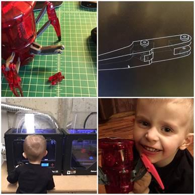
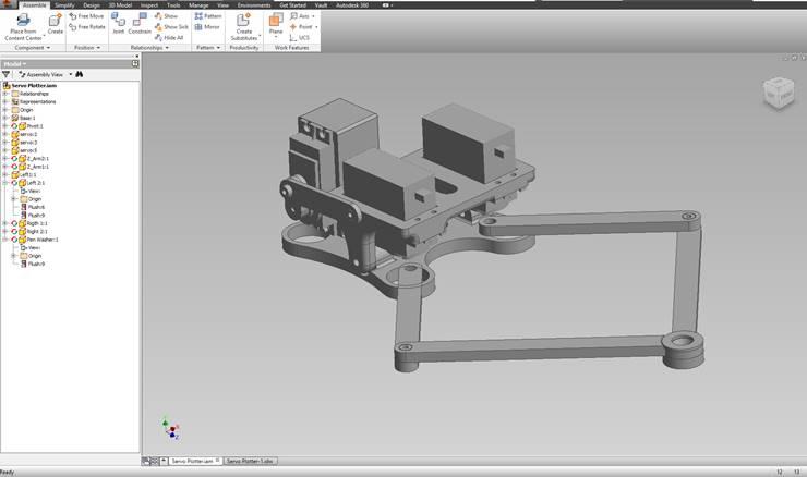
This bit of father/son afternoon tinkering required more than just a couple of tools from the garage. Instead, they went to the computer. The first prototypes were designed using Trimble SketchUp and, after a bit of tweaking for practical and aesthetic purposes, the final design was created in Autodesk Inventor Pro. For the creation of the pieces of the automated pantograph they turned to a MakerBot Replicator 2X to create the 3D printed parts and in the time that it takes to read the entire owner’s manual for a 1985 Honda Civic (four hours) they had all the printed parts they needed.
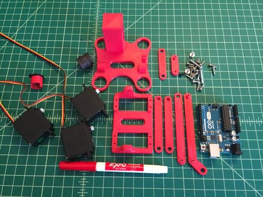
To complete their project, they purchased the remaining parts: 3 servos, 5 magnets, felt, a dry erase marker, an Arduino Uno, and a variety of fasteners. Boe, who in his time away from fathering is an industrial engineer for Schenker Logistics, explained the principle behind the functioning of the automated pantograph:
“The machine can plot on a 2D surface using Gcode. To create the bitmap plots, I convert an image into an excel matrix of 0’s and 1’s, using a formula that would convert the presence of an image to a 1 and the absence to a 0. I then copy that text from excel and paste it into the Arduino code.”
In other words, you shouldn’t expect subtle gradations and life-like, photo-realistic renderings from the pantograph, but then, that’s why we have full color printers anyway. What’s really cool here is the fact that it’s a family project and it actually works! Boe uploaded a video to YouTube of the machine hard at work introducing itself to the world by writing “hello world” on a dry erase board–check it out above. It’s hard not to anthropomorphize the creature a bit and see it as a near living thing.
Now, at least, my children will be wondering what happens when they use an Arduino controlled pantograph to draw on the wall in permanent marker.