
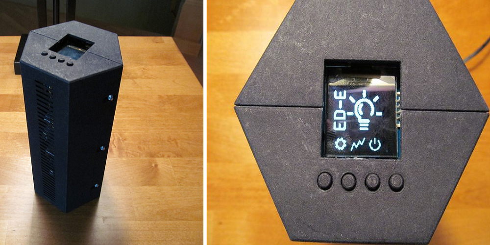
The ED-E (EDison-Esp8266, pronounced Eddie) is composed of the WiFi unit and the base unit–which is the brains of the operation, built with an:
- Intel Edison with local MySQL database
- OLED display
- Analytics dashboard with real-time graphs
- Six sensors
- Four push buttons for user input and output devices
- Emergency buzzer
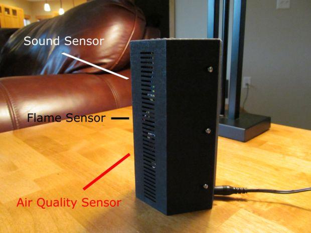
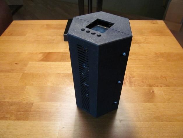
All of this is encompassed within a 3D printed console. Not only does the ED-E detect suspicious activity in your home, it also alerts you if there is a high level of gas or bad air. When that happens, a buzzer sounds from the base unit, as well as sending you an email. Six sensors alert you to: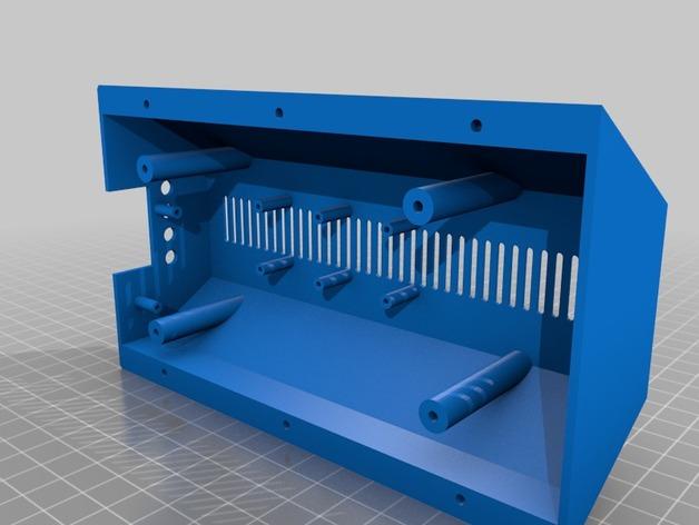
- Flame
- Gas (H2, LPG, CH4, CO, Alcohol, Smoke, Propane)
- Air Quality (carbon monoxide, alcohol, acetone, thinner, formaldehyde)
- Temperature
- Humidity
- Sound
The WiFi units are made up of small transmitters that communicate with you regarding your home. The ED-E supports WiFi sensors and WiFi actuators.
The sensors have a detention circuit that, when triggered, sends a transmission to the analytics cloud. As with a traditional system, these WiFi sensors can be placed on doors, windows, and even mailboxes.
The actuators are used to trigger events rather than respond to them. They can be used to turn your lights on, start the coffee, or even open the garage–from anywhere in the world. With nearly all WiFi units supported, Tyler states that ‘the possibilities are endless.’
For the base unit, you will need:
- Intel Edison with Arduino Breakout
- Adafruit Permaproto Half-sized breadboard
- Grove Air Quality Sensor
- Grove MQ2 Gas Sensor
- Grove DHT22 Temperature and Humidity Sensor
- Grove Sound Sensor
- Grove Flame Sensor
- Grove 96×96 OLED Display
- Grove Buzzer
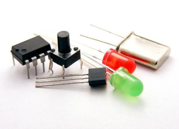
- 0.1″ Male Headers
- DC Barrel Jack
- 10K Resistors
- 6mm Tactile Pushbuttons
- Lots of wire
For the WiFi Sensors you will need:
- Adafruit HUZZAH Esp8266
- 500mah Battery
- JST connector breakout
- Micro Switch
For the WiFi Actuators you will need:
- Adafruit HUZZAH Esp8266
- Grove Relay (SPDT)
- 5V Power Supply (Like a phone charger)
- Short power strip
First, you’ll want to start with the base unit, connecting the sensors to the Intel board. All of the sensors use the same 4 wire connector, and as you’ll see from the Instructable, there is a wire for ground, power, and signal line. Read the instructions further for specific notes on what to cut and solder.
- Connect the red power wire to 3.3v.
- Connect the black ground wire to ground.
- Connect the yellow signal wire (SCL) to A5.
- Connect the white signal wire to (SDA) A4.
Next, it’s time to add the buttons and the power jack to the base unit by reading the list of soldering and connecting instructions. After that you want to connect the DC barrel jack, carefully.
“Be extra careful nothing is shorted out, as you wouldn’t want 12 volts wandering into the Edison where it doesn’t belong,” warns Tyler.
Next, you need to install and also test the software. See here for the full instructions on installing dependencies, analytics, and running it ‘on boot.’
The last time is final assembly of the system, which includes gluing the button protoboard into place with the 3D printed button rig wedged between the model and board. After that, screw in the sensors, display, and Intel Edison + Arduino Breakout to the big standoffs. Follow the more detailed instructions to make sure you have everything correct and attached safely. Once you’ve finished with final assembly, you are ready to monitor and automate your home like a pro.
Will you be taking on this project? Let us know how it turns out in the 3D Printed Home Monitor forum thread on 3DPB.com.
